
Angle-adjustable steel plate cutter

An adjustable, cutting machine technology, applied in shearing devices, accessories of shearing machines, metal processing machinery parts, etc. The effect of processing and use, reducing labor intensity and protecting personnel safety

Inactive Publication Date: 2017-07-21
惠安县鑫泰信息科技有限公司
View PDF0 Cites 14 Cited by
  • Summary
  • Abstract
  • Description
  • Claims
  • Application Information

AI Technical Summary

Problems solved by technology

[0002] With the development of society and the improvement of people's living standards, people's demand for resources also increases. Steel is an indispensable resource in people's daily life and construction. However, when producing steel, it is necessary to divide the raw materials of steel. Sectional cutting is convenient for later processing. Manual cutting is time-consuming and laborious, and the work efficiency is slow. The splashed sawdust will enter the eyes, which poses a safety hazard; although some existing cutting machines can realize the cutting of steel plates, the steel plates after cutting are often Right-angle cutting surface, the cutting machine has poor adaptation effect and is not flexible enough to use; in addition, when the steel plate moves on the frame, due to the high friction, the implementation is slow, time-consuming and laborious, which affects the steel plate processing. Therefore, the existing cutting machine needs to be improved. , to meet the needs of modern processing

Method used


Image

  • Angle-adjustable steel plate cutter
  • Angle-adjustable steel plate cutter

Examples


Embodiment Construction

[0016] The following will clearly and completely describe the technical solutions in the embodiments of the present invention with reference to the accompanying drawings in the embodiments of the present invention. Obviously, the described embodiments are only some, not all, embodiments of the present invention. Based on the embodiments of the present invention, all other embodiments obtained by persons of ordinary skill in the art without making creative efforts belong to the protection scope of the present invention.

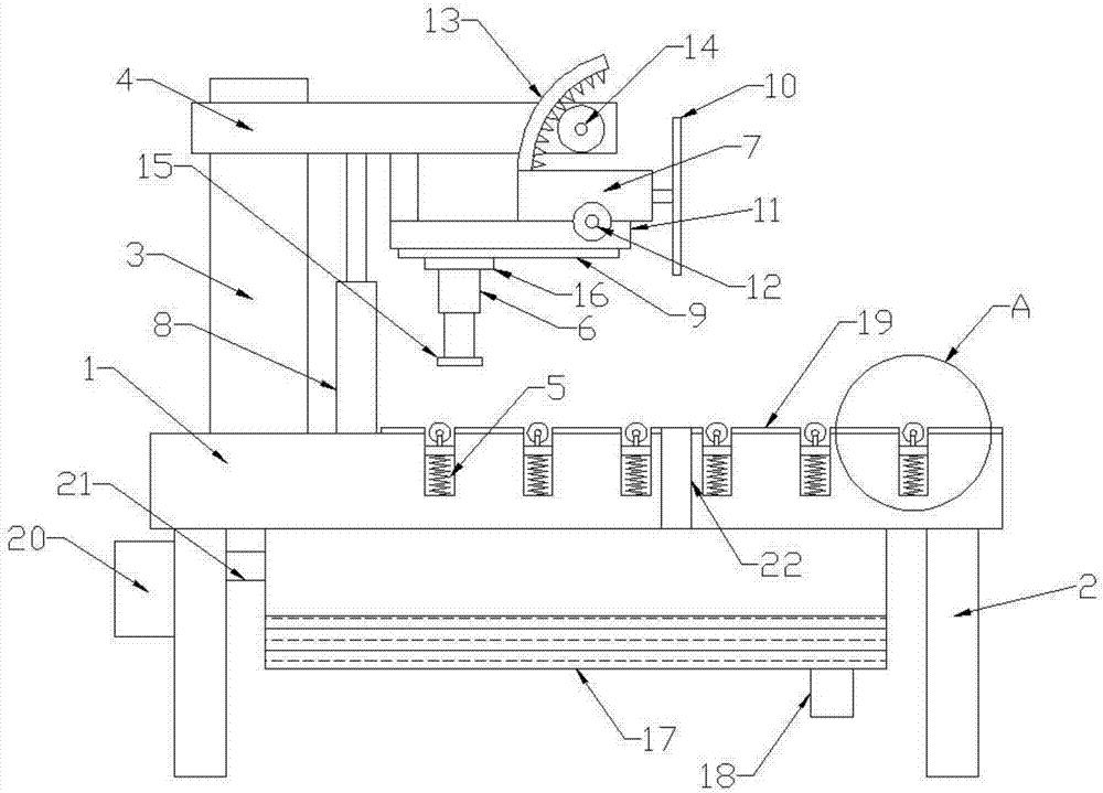
[0017] Please refer to the figure, in the embodiment of the present invention, an angle-adjustable steel plate cutting machine includes a platform 1, legs 2, columns 3 and beams 4; the legs 2 are fixedly welded to the left and right ends of the platform 1, and the columns 3 Fixedly welded on the left side of the platform 1, the beam 4 is fixedly installed on the column 3, the mounting frame 11 is fixedly mounted on the lower side of the beam 4, the rotating sha...


PUM

PropertyMeasurementUnit
thicknessaaaaaaaaaa

Abstract

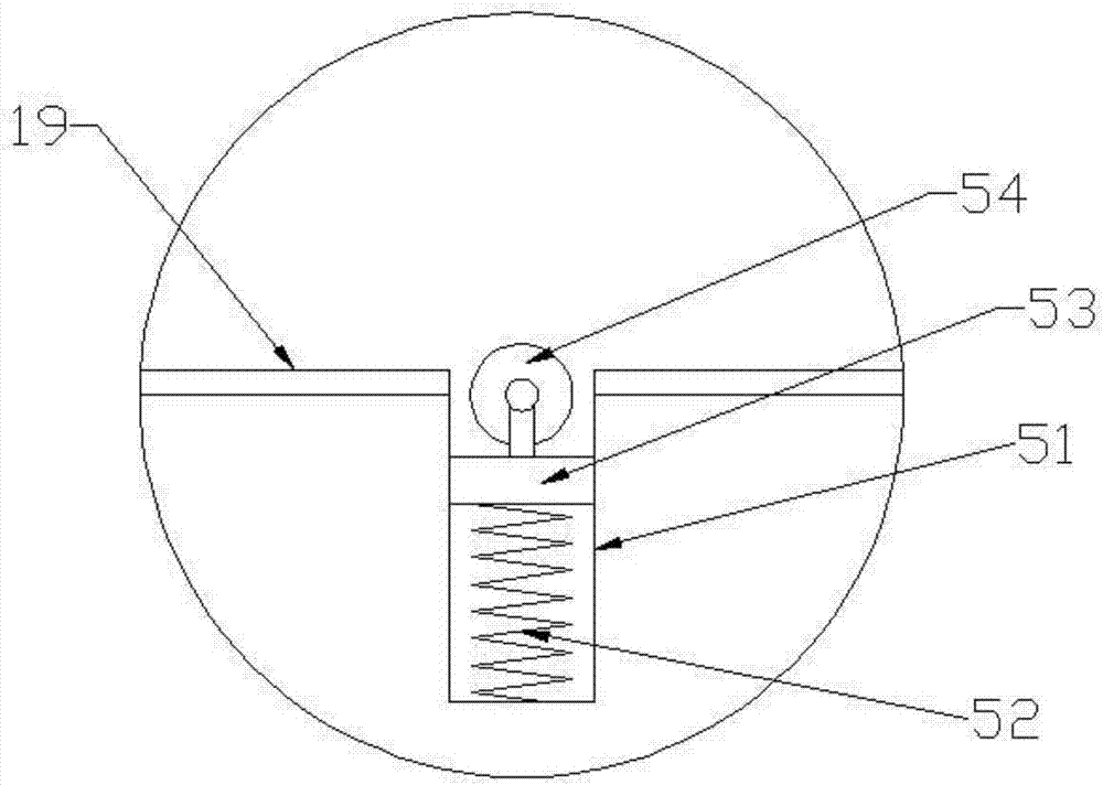
The invention discloses an angle-adjustable steel plate cutting machine, which comprises a platform, supporting legs, uprights and beams; a mounting frame is fixedly installed on the lower side of the beam; a rotating shaft is installed on the end of the mounting frame; ; The upper side of the motor is fixedly connected with an arc-shaped guide rod, and a plurality of equidistant teeth are arranged on the lower side of the guide rod, and a gear is connected through the meshing of the teeth, and a water tank is communicated below the cutting opening; Several supporting mechanisms are arranged on the platform and on both sides of the cutting opening, and the supporting mechanisms are composed of grooves, springs, supporting plates and guide wheels. The invention supports the steel plate through the support mechanism, so that the steel plate can easily move left and right on the platform, reducing the labor intensity of workers; the gear drives the guide rod to move, so that the motor rotates around the rotating shaft, and the cutting of the steel plate forms an angle with the horizontal plane. Surface cutting, so that the cutting machine has a variety of functions to meet more production needs.

Description

technical field [0001] The invention relates to steel processing equipment, in particular to a steel plate cutting machine with adjustable angle. Background technique [0002] With the development of society and the improvement of people's living standards, people's demand for resources also increases. Steel is an indispensable resource in people's daily life and construction. However, when producing steel, it is necessary to divide the raw materials of steel. Sectional cutting is convenient for later processing. Manual cutting is time-consuming and laborious, and the work efficiency is slow. The splashed sawdust will enter the eyes, which poses a safety hazard; although some existing cutting machines can realize the cutting of steel plates, the steel plates after cutting are often Right-angle cutting surface, the cutting machine has poor adaptation effect and is not flexible enough to use; in addition, when the steel plate moves on the frame, due to the high friction, the i...

Claims


Application Information

Patent Timeline
Patent Type & Authority Applications(China)
IPC IPC(8): B23D19/08B23D33/02B23Q11/00
CPCB23D19/08B23D33/02B23Q11/005
Inventor 不公告发明人
Owner 惠安县鑫泰信息科技有限公司
Learn More