
Universal Fiber Splice Tray

A kind of optical fiber fusion splicing disk, general-purpose technology, applied in the direction of optics, light guides, optical components, etc., can solve the problems of limited number of optical cable fusion protection lines, inconvenient maintenance and operation of fusion splicing chips, and the inability to further increase the capacity of unit equipment, etc.

Active Publication Date: 2020-04-17
CHANGZHOU TAIPING COMM SCI & TECH
View PDF33 Cites 0 Cited by
  • Summary
  • Abstract
  • Description
  • Claims
  • Application Information

AI Technical Summary

Problems solved by technology

For splicing chips with 12 cores or more, one is to stack the splicing fibers in the card slot. This stacking method will bring great inconvenience to the maintenance operation of the splicing chips in the future.
The other is to increase the area of ​​the fusion chip to increase the number of fusion partitions. Although it can simplify maintenance operations, it occupies a large area. Due to the limited number of optical cable fusion protection lines, it is impossible to further increase the capacity of the unit equipment and cannot meet the needs of multi-core optical fibers. Splicing protection and storage

Method used


Image

  • Universal Fiber Splice Tray
  • Universal Fiber Splice Tray
  • Universal Fiber Splice Tray

Examples


Embodiment Construction

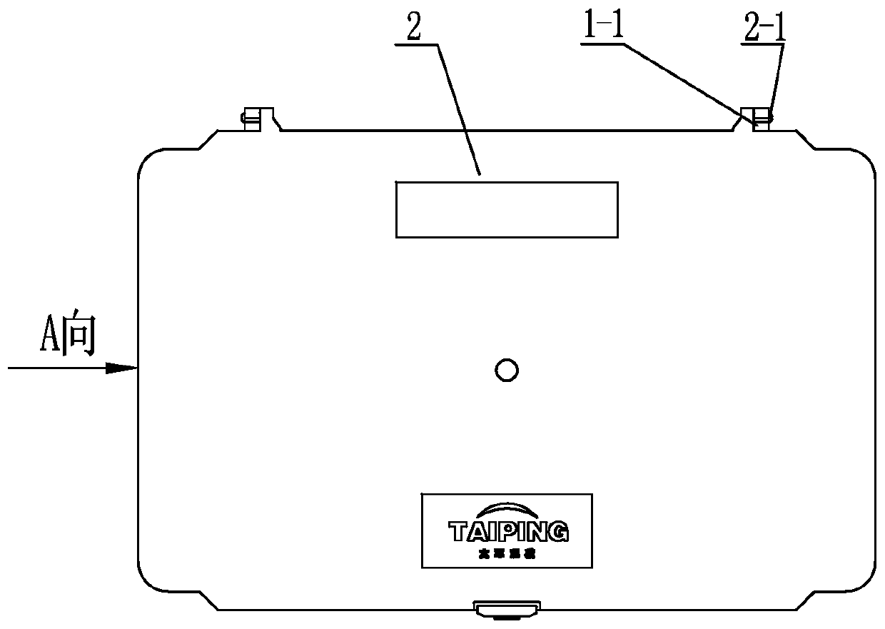
[0033] See Figure 1~5 As shown, the general-purpose optical fiber fusion splicing tray of the present invention includes a fusion splicing base plate 1 and a cover plate 2. The fusion splicing base plate 1 includes an integrated bottom plate 1-3 and wall panels around the bottom plate 1-3. The cover plate 2 is hinged on the fusion splicing base plate. On the rear wall panel 1-2 of the tray 1, the fusion splice optical fiber in the fusion splicing base tray 1 is protected by the cover plate 2. See Figure 1~5 As shown, the two sides of the upper part of the rear wall panel 1-2 of the welding base plate 1 of the present invention are provided with an integrated rotating shaft sleeve 1-1, and the two rotating shafts 2-1 corresponding to the rear side of the cover plate 2 are arranged on the rotating shaft of the welding base plate 1 The sleeve 1-1 can also rotate along the center of the shaft sleeve 1-1, and the cover plate 2 can also be provided with a shaft sleeve, and the we...


PUM


Abstract

The invention relates to a universal optical fiber fusion splice protector, which comprises a fusion splice base plate and a cover plate, wherein the fusion splice base plate comprises an integral bottom plate and wall plates around the bottom plate; the bottom plate is provided with outer partition plates, inner partition plates and optical fiber fusion splice protection areas formed between the inner and outer partition plates on the inner sides of the front and rear wall plates; redundant optical fiber storage areas are formed between each side partition plate and the corresponding side wall plate and between each outer partition plate and the corresponding front wall plate and rear wall plate; a bunched optical cable fusion splice chip and a ribbon optical cable fusion splice chip are detachably arranged at the corresponding optical fiber fusion splice protection areas; movable elastic pressure blocks are arranged on the two sides of the bunched optical cable fusion splice chip and / or the two sides of the ribbon optical cable fusion splice chip on the bottom plate. According to the universal optical fiber fusion splice protector, the fusion splice protection and storage of bunched and ribbon optical cables can be met at the same time, movable clamping groove areas can be formed to protect fusion splice points of optical fibers of each core, the universal optical fiber fusion splice protector is reasonable in structure and convenient to maintain and operate, the number of optical cable fusion splice protection lines can be increased in a finite space, and a route can be kept clear.

Description

technical field [0001] The invention relates to a general-purpose optical fiber fusion splice tray, which belongs to the technical field of outdoor optical cable distribution. Background technique [0002] With the rapid development of global information technology, people's demand for bandwidth is increasing day by day. With the deployment of 4G and high-speed optical fiber networks, the optical communication market has also ushered in a new round of market opportunities. Under the multiple impetus of demand, technology, market and policy, China has become an important market for optical fiber and cable in the world. More than half of the world's fiber optic cables are produced and sold in China. China has become the manufacturing center and marketing center of the global fiber optic cable industry, and will become a research and development center, consulting and service center in the future. [0003] With the development of the Internet and cloud computing, optical commu...

Claims


Application Information

Patent Timeline
Patent Type & Authority Patents(China)
IPC IPC(8): G02B6/255
CPCG02B6/2556G02B6/2558
Inventor 时同军王绪章任献忠石新根吴锦辉
Owner CHANGZHOU TAIPING COMM SCI & TECH
Learn More