
Uplink signal sending method and device

A signal transmission device and a signal transmission technology are applied in the directions of pilot signal allocation, transmission path separation device, wireless communication, etc., and can solve the problem that uplink demodulation reference signals cannot be transmitted by sub-carriers.

Active Publication Date: 2017-07-18
ZTE CORP
View PDF5 Cites 28 Cited by
  • Summary
  • Abstract
  • Description
  • Claims
  • Application Information

AI Technical Summary

Problems solved by technology

[0004] In order to solve the above technical problems, the present invention provides a method and device for sending uplink signals. The present invention solves the problem that the uplink demodulation reference signal cannot be sent using subcarriers as the scheduling unit in the prior art by rationally designing the uplink data sending method. The problem

Method used


Image

  • Uplink signal sending method and device
  • Uplink signal sending method and device
  • Uplink signal sending method and device

Examples


Embodiment Construction

[0115] In order to make the purpose, technical solution and advantages of the present invention more clear, the embodiments of the present invention will be described in detail below in conjunction with the accompanying drawings. It should be noted that, in the case of no conflict, the embodiments in the present application and the features in the embodiments can be combined arbitrarily with each other.

[0116] The steps shown in the flowcharts of the figures may be performed in a computer system, such as a set of computer-executable instructions. Also, although a logical order is shown in the flowcharts, in some cases the steps shown or described may be performed in an order different from that shown or described herein.

[0117] The technical solutions of the present invention will be described in detail below through specific embodiments. The terminal devices in the following embodiments of the present invention may be, for example, terminal devices in the Internet of Thin...


PUM


Abstract

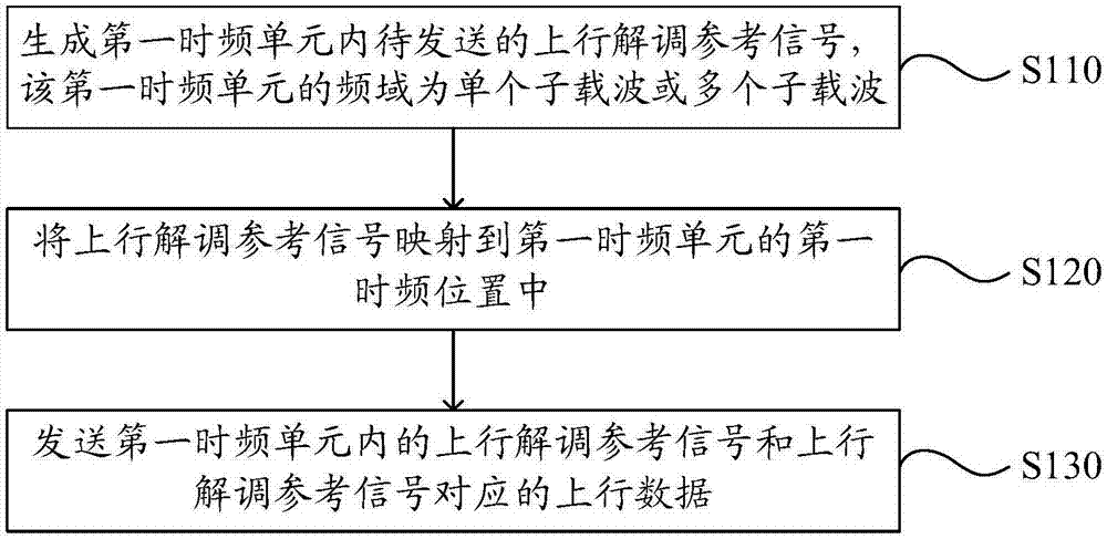
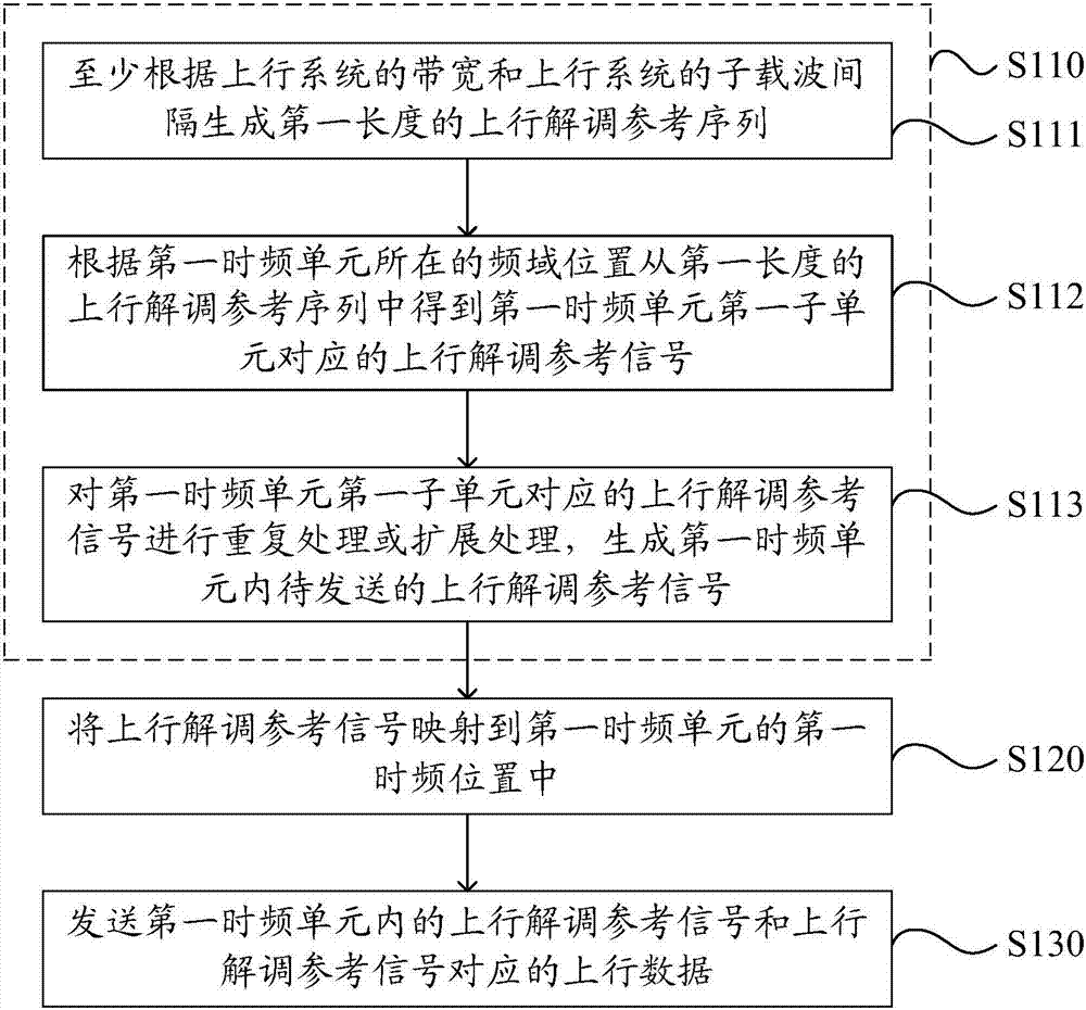
The invention discloses an uplink signal sending method and device. The uplink signal sending method includes generating to-be-sent uplink demodulation reference signals in a first time frequency unit, wherein the frequency domain of the first time frequency unit is a single sub carrier or a plurality of sub carriers; mapping the uplink demodulation reference signals to a first time frequency position of the first time frequency unit; sending the uplink demodulation reference signals in the first time frequency unit and uplink data corresponding to the uplink demodulation reference signals. According to the invention, through reasonable design of the uplink data sending method, a problem that the uplink demodulation reference signals cannot be sent by taking the sub carrier as the modulation unit in the prior art is solved.

Description

technical field [0001] The present invention relates to the technical field of wireless communication, in particular to an uplink signal sending method and device. Background technique [0002] With the development of wireless communication technology, in mobile network applications, the demand for traffic, the number of terminals and the types of terminals all show an explosive growth trend. The fifth generation mobile communication technology (5th Generation, referred to as: 5G) has become The trend of future network development. Machine Type Communication (MTC for short), as one of the important scenarios and technical means of the 5G system, has received more and more attention. [0003] MTC, also known as machine-to-machine (M2M) communication, is a main application form of the Internet of Things at the present stage. Currently, the MTC devices deployed in the market are mainly based on the Global System of Mobile communication (GSM) system, and several of them are di...

Claims


Application Information

Patent Timeline
IPC IPC(8): H04L27/26
CPCH04L27/261H04L27/2613H04L5/0048H04L27/26132H04L5/0007H04J13/0062H04L1/1812H04L5/0023H04W72/0446
Inventor 杨维维戴博夏树强方惠英
Owner ZTE CORP
Learn More