
LINC transmitter

A transmitter and radio frequency signal technology, applied in the direction of electrical components, transmission systems, communication between multiple stations, etc., can solve problems such as difficulties, unbalanced amplitude gain, complex trigonometric functions of arccosine functions, etc., to improve linearity , Improve work performance and avoid signal distortion

Inactive Publication Date: 2010-06-09
UNIV OF ELECTRONIC SCI & TECH OF CHINA
View PDF11 Cites 19 Cited by
  • Summary
  • Abstract
  • Description
  • Claims
  • Application Information

AI Technical Summary

Problems solved by technology

[0003] General wireless communication transmitters cannot meet the requirements of high efficiency and high linearity at the same time
Usually designers either achieve high efficiency indicators alone or high linearity indicators alone. These transmitters that cannot take into account both efficiency and linearity have been unable to adapt to the development of modern communication technology.
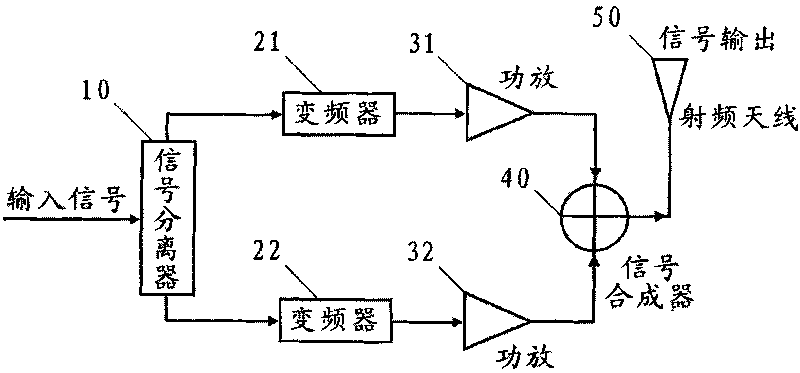
In the 1930s, Chireix proposed outphasing modulation (Outphasing Modulation) technology, which realized the design idea of ​​using nonlinear power amplifiers to improve transmitter efficiency, but designers at that time were more inclined to rely on improved device materials to improve power amplifiers. efficiency, and due to the complexity of implementing the arccosine or other trigonometric functions in analog circuits, this technique has not received the attention it deserves
[0005] In the research and practice of the prior art, the inventor has found that the traditional LINC transmitter has at least the following problems: the LINC transmitter is very sensitive to the unbalance of the amplitude gain of the two anti-phase signals after separation, and the two-way amplifier branch Gain imbalance seriously affects the linearity of LINC transmitter
In addition, due to temperature drift, device aging, and channel change, the amplitude characteristics of the transmitter will continue to change, so it is very difficult to design a LINC transmitter with better performance in practical applications

Method used

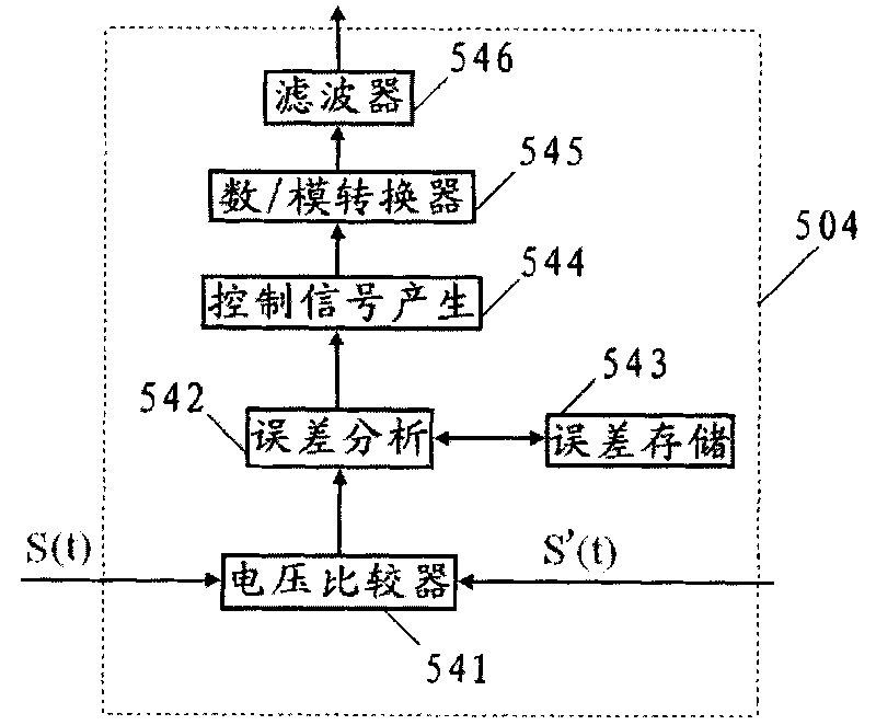

Image

  • LINC transmitter
  • LINC transmitter
  • LINC transmitter

Examples


Embodiment Construction

[0025] The present invention will be described in further detail below with reference to the accompanying drawings.

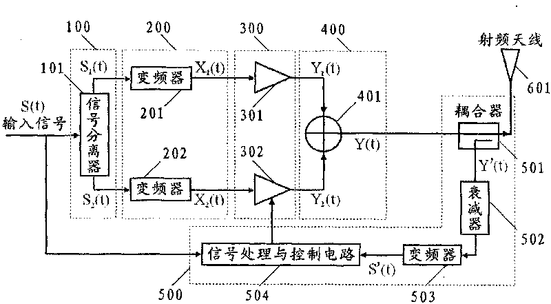
[0026] The LINC transmitter provided by the present invention, such as figure 2 shown, including:

[0027] The signal separation unit 100 decomposes the baseband input signal into two anti-phase signals with equal envelope amplitudes but unequal phases. The unit includes at least one signal splitter 101 .

[0028] Baseband input signal S (t)=a(t)cos(ωt+θ) input signal separator 101 carries out signal separation processing, and signal separator 101 carries out reverse-phase separation to baseband input signal S (t) based on digital signal processing technology, Its specific separation algorithm is consistent with the traditional LINC transmitter separation algorithm, which is a well-known technology, so it will not be described in detail here. The signal splitter 101 should include a digital / analog (D / A) converter, which converts the separated two-way digita...


PUM


Abstract

The invention provides an LINC transmitter, belongs to the technical field of wireless communication, and relates to a transmitting apparatus in wireless communication technology, in particular to a linear amplification with nonlinear components (LINC)-based transmitter. The LINC transmitter comprises a signal separating unit, a variable-frequency unit, a signal amplifying unit, a signal synthesizing unit, a radio-frequency antenna and a feedback control unit, wherein the feedback control unit couples partial output signals; the partial output signals are subjected to attenuation and down-conversion and then compared with an input signal to obtain an error signal; the error signal is utilized to perform real-time regulation and control on the output power of any power amplifier in the signal amplifying unit so as to realize gain balance between a first switch type power amplifier and a second switch type power amplifier in the signal amplifying unit. The output power of the switch type power amplifiers in the LINC transmitter is fed back and controlled and the gain imbalance between two paths of signals are eliminated so as to improve the linearity of the LINC transmitter and enable the LINC transmitter to realize high-efficiency and high-linearity amplification on a wireless communication signal.

Description

technical field [0001] The invention belongs to the technical field of wireless communication, and relates to a transmitting device of the wireless communication technology, in particular to a transmitter based on a nonlinear device linearization technology (LINC). Background technique [0002] With the development of modern wireless communication technology, the modulation method of radio frequency communication signal is gradually complicated, and the envelope amplitude of the modulated signal has obvious random characteristics, which puts forward high requirements on the linearity of the power amplifier at the end of the transmitter. In addition, there is an obvious defect in the existing wireless communication transmitters - low working efficiency, large power loss, and additional cooling devices or even refrigeration equipment are required to maintain the stable operation of the system. This obviously increases the economic cost and is contrary to the modern system desi...

Claims


Application Information

Patent Timeline
IPC IPC(8): H04B1/02H04B7/26
Inventor 何松柏曹韬李晓东尹世荣
Owner UNIV OF ELECTRONIC SCI & TECH OF CHINA
Learn More