
Mist imaging device

The technology of an imaging device and a water mist generating device, which is applied in display devices, projection devices, optics, etc., can solve the problems of water mist imaging equipment, such as fixed structure, poor flexibility and imaging quality, and flexible adjustment of equipment mechanism, so as to improve flexibility. Excellent performance and site adaptability, low operation and maintenance costs, and flexible and convenient use

Inactive Publication Date: 2017-07-18
GUANGZHOU SHUIYIFANG INFORMATION TECH CO LTD
View PDF4 Cites 11 Cited by
  • Summary
  • Abstract
  • Description
  • Claims
  • Application Information

AI Technical Summary

Problems solved by technology

[0002] At present, water mist imaging equipment has been widely used in exhibition hall information display, music fountain and other fields. Although the currently used water mist imaging device can effectively meet the needs of imaging operations, on the one hand, when imaging, it is mainly through Projection equipment regulates imaging confidence and quality. On the other hand, when imaging, the current water mist equipment can only provide water mist for imaging, but lacks effective adjustment and light compensation capabilities for the virtual image information on the water mist. , resulting in relatively poor operating flexibility and imaging quality of the current water mist imaging equipment, which cannot effectively meet the needs of actual use. In addition, the current water mist imaging equipment has a relatively fixed structure. During operation, it cannot The flexible adjustment of the equipment structure according to the needs of use and the environmental conditions of the site greatly limits the flexibility and reliability of the water mist imaging equipment. Therefore, in view of this situation, it is urgent to develop an inventive water mist imaging device to meet practical needs

Method used


Image

  • Mist imaging device

Examples


Embodiment Construction

[0014] In order to make the technical means, creative features, goals and effects achieved by the present invention easy to understand, the present invention will be further described below in conjunction with specific embodiments.

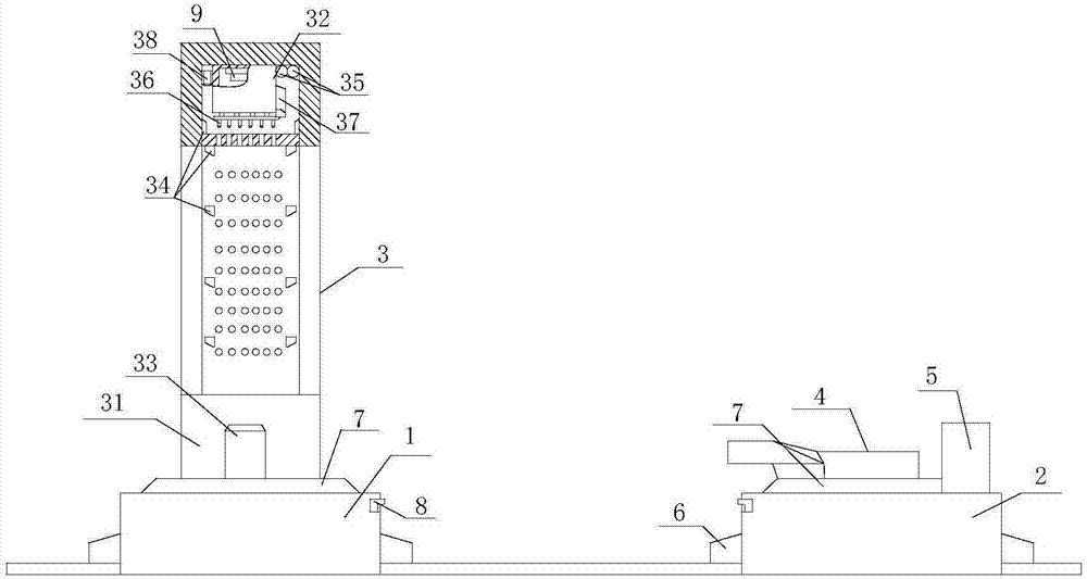
[0015] Such as figure 1 The described water mist imaging device includes a base 1, a slide rail 2, a water mist generating device 3, a projection imaging device 4 and a control system 5. There are at least two bases 1, and each base 1 passes through at least one The slide rails 3 are connected to each other and distributed in the same straight line direction, and the base 2 is slidingly connected with the slide rails 3 through the traveling mechanism 6, and the water mist generating device 3 is installed on the base 1 located at the front end of the slide rail 2, and is connected with the base The seat 1 is coaxially distributed, and the projection imaging device 4 and the control system 5 are installed on the base 1 positioned at the rear side of...


PUM


Abstract

The invention relates to a mist imaging device which comprises a base, a sliding track, a mist generation device, a projection imaging device and a control system, wherein the base is in sliding connection with the sliding track through a walking mechanism; the mist generation device is mounted on the base at the most front end of the sliding track; the projection imaging device and the control system are mounted on the base on the rear side of the mist generation device; the optical axis of the projection imaging device crosses the middle point of the mist generation device and is in an included angle of 15-90 degrees with the surface of the projection imaging device; the control system is electrically connected with the mist generation device, the projection imaging device and the walking mechanism respectively; the mist generation device comprises a holding rack, buffer water tanks, charging pumps, ultrasonic wave atomization devices, guide tubes, atomization nozzles, jet flow pumps and compensation light sources. On one hand, the mist imaging device is capable of effectively meeting requirements of mist imaging operation, on the other hand, the requirement that various types of images and video information are imaged in a mist manner can be flexibly met according to use demands.

Description

technical field [0001] The invention relates to a virtual imaging device, specifically a water mist imaging device. Background technique [0002] At present, water mist imaging equipment has been widely used in exhibition hall information display, music fountain and other fields. Although the currently used water mist imaging device can effectively meet the needs of imaging operations, on the one hand, when imaging, it is mainly through Projection equipment regulates imaging confidence and quality. On the other hand, when imaging, the current water mist equipment can only provide water mist for imaging, but lacks effective adjustment and light compensation capabilities for the virtual image information on the water mist. , resulting in relatively poor operating flexibility and imaging quality of the current water mist imaging equipment, which cannot effectively meet the needs of actual use. In addition, the current water mist imaging equipment has a relatively fixed structur...

Claims


Application Information

Patent Timeline
IPC IPC(8): G09F19/18G03B21/608
CPCG09F19/18G03B21/608
Inventor 易华斌
Owner GUANGZHOU SHUIYIFANG INFORMATION TECH CO LTD
Learn More