Microwave frequency measuring method and device based on optics frequency comb

A microwave frequency measurement and optical frequency comb technology, applied in frequency measurement devices, measurement devices, measurement of electrical variables, etc., can solve the problems of poor real-time performance, measurement accuracy only in the order of GHz, and measurement accuracy is not uniform, and achieve frequency measurement. The effect of small error and high measurement resolution

Inactive Publication Date: 2017-07-18
HARBIN INST OF TECH
View PDF4 Cites 12 Cited by
  • Summary
  • Abstract
  • Description
  • Claims
  • Application Information

AI Technical Summary

Problems solved by technology

The commonly used microwave power mapping method can generally perform frequency measurement within the frequency range of 20GHz, but it can only measure the frequency of single-frequency signals, and the measurement accuracy is not uniform; the frequency measurement of the channel method can be realized in a larger range. Frequency measurement, but its measurement accuracy is only on the order of GHz; the scanning method can measure high-precision frequency of multi-frequency microwave signals in a wide range, but its real-time performance is poor, and instantaneous frequency measurement cannot be performed

Method used


Image

  • Microwave frequency measuring method and device based on optics frequency comb
  • Microwave frequency measuring method and device based on optics frequency comb
  • Microwave frequency measuring method and device based on optics frequency comb

Examples


Embodiment Construction

[0031] The present invention will be described in further detail below in conjunction with the accompanying drawings: the present embodiment is implemented on the premise of the technical solution of the present invention, and detailed implementation is provided, but the protection scope of the present invention is not limited to the following embodiments.

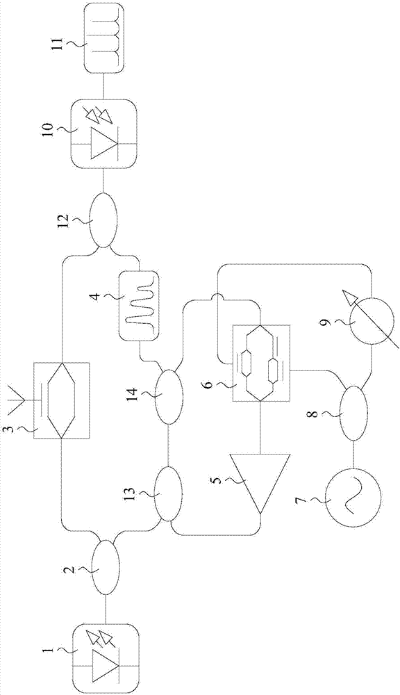
[0032] Such as figure 1 As shown, a method for measuring microwave frequency based on an optical frequency comb involved in this embodiment, the steps are as follows:

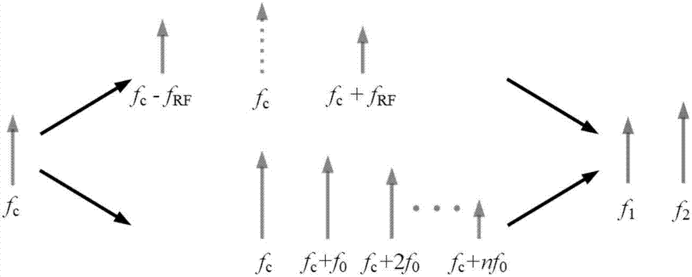
[0033] Step 1. The frequency f is generated by the laser c The laser signal is divided into two parts, one of which is composed of frequency f RF Carrier-suppressed double-sideband modulation is performed on the unknown RF signal, and the modulated signal light field is approximately expressed as:

[0034] E. u (t)=E 0 sin[βcos(2πf RF t)]≈A +1 cos[2π(f c +f RF )t]+A -1 cos[2π(f c -f RF )t] (1)

[0035] where A ±1 =J 1 (β) is the amplitude of t...


PUM


Abstract

The invention provides a microwave frequency measuring method and device based on an optics frequency comb, and belongs to the microwave frequency measuring method and device technical field; the method comprises the following steps: dividing a laser signal formed by a laser and with the frequency fc into two parts, and using an unknown RF signal with the frequency fRF to carry out carrier suppression double-sideband modulation for one of the said two parts; beating frequencies of a carrier suppression double-sideband modulation signal and an off resonance light frequency comb on a narrowband photoelectric detector; parsing the frequency spectrum of the beat frequency signals, thus obtaining frequency information and power information of the two beat frequency signals; determining the frequency of the incident RF signal according to determined i, f1, f2 and a formula (7). The measuring device comprises the laser, a first coupler, an intensity modulator, a programmable filter, an erbium doped fiber amplifier, a double parallel modulator, a signal-generator, an electricity coupler, a phase shifter, a photoelectric detector, a frequency spectrograph, a second coupler, a third coupler and a fourth coupler.

Description

technical field [0001] The invention relates to a microwave frequency measurement method and device based on an optical frequency comb, and belongs to the technical field of microwave frequency measurement methods and devices. Background technique [0002] At present, a major problem in the field of photonics microwave frequency measurement is how to measure the frequency of microwave signals with high precision in a large frequency measurement range. The commonly used microwave power mapping method can generally perform frequency measurement within the frequency range of 20GHz, but it can only measure the frequency of single-frequency signals, and the measurement accuracy is not uniform; the frequency measurement of the channel method can be realized in a larger range. Frequency measurement, however, its measurement accuracy is only on the order of GHz; the scanning method can measure high-precision frequency of multi-frequency microwave signals in a wide range, but its rea...

Claims


Application Information

Patent Timeline
IPC IPC(8): G01R23/14
CPCG01R23/145
Inventor 沈志强张勇曹力赵远吴昊贺群淞
Owner HARBIN INST OF TECH
Why Eureka
Try Eureka