
Vehicle dipped headlight set and vehicle with same

A technology for low beams and vehicles, applied in the field of vehicles, can solve the problems of low utilization rate of light energy, loss of light energy, reduction of light, etc., and achieve the effects of wide illumination range, increased driving safety, and increased range

Active Publication Date: 2017-07-14
BYD CO LTD
View PDF18 Cites 10 Cited by
  • Summary
  • Abstract
  • Description
  • Claims
  • Application Information

AI Technical Summary

Problems solved by technology

The LED light source is arranged in the spherical center of the hemispherical inner surface at the rear end of the lens, the bottom is connected with the radiator, and the reflective bowl and radiator are fixed on the bracket. In this structure, the low beam light pattern mainly depends on the light pattern baffle to block part of the light. On the one hand, part of the light energy is lost due to the shading of the baffle, and the light energy utilization rate is low; on the other hand, the actual light in the upper space of the lens corresponding to the light-type baffle is reduced, thus wasting most of the space in the structure; Third, because the lens must first consider the light type requirements of the light and dark cut-off line of the law, the light distribution design cannot achieve the widened light distribution design at the same time, which affects the driver's field of vision

Method used


Image

  • Vehicle dipped headlight set and vehicle with same
  • Vehicle dipped headlight set and vehicle with same
  • Vehicle dipped headlight set and vehicle with same

Examples


Embodiment Construction

[0043] Embodiments of the invention are described in detail below, examples of which are illustrated in the accompanying drawings. The embodiments described below by referring to the figures are exemplary and are intended to explain the present invention and should not be construed as limiting the present invention.

[0044] In describing the present invention, it should be understood that the terms "center", "longitudinal", "transverse", "length", "width", "thickness", "upper", "lower", "front", " Back", "Left", "Right", "Vertical", "Horizontal", "Top", "Bottom", "Inner", "Outer", "Clockwise", "Counterclockwise", "Axial", The orientation or positional relationship indicated by "radial", "circumferential", etc. is based on the orientation or positional relationship shown in the drawings, and is only for the convenience of describing the present invention and simplifying the description, rather than indicating or implying the referred device or element Must be in a particular ...


PUM


Abstract

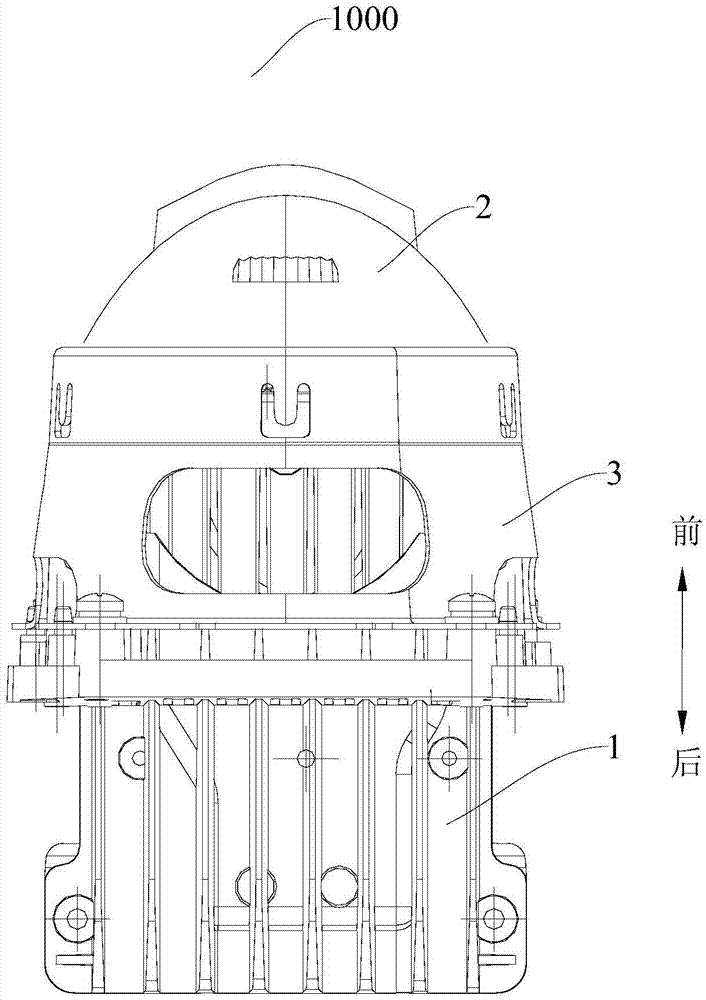
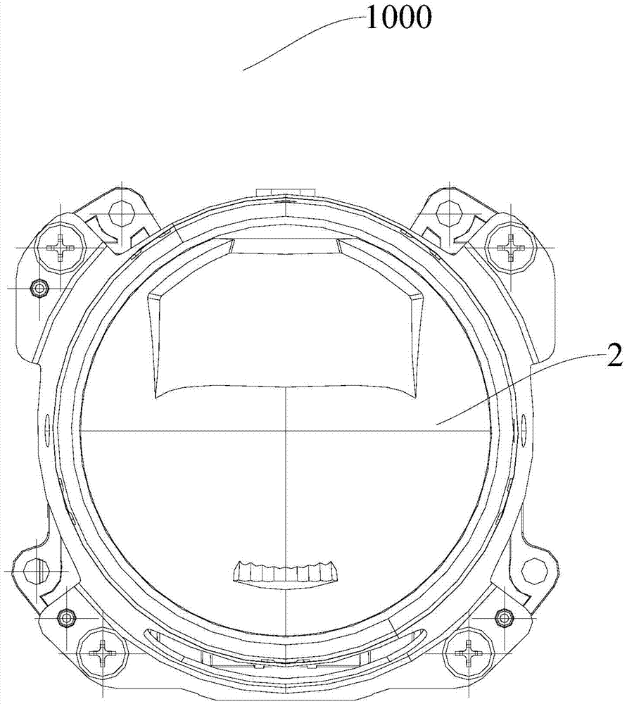
The invention discloses a vehicle dipped headlight set and a vehicle with the same. The vehicle dipped headlight set comprises a fixed support, a lens assembly, a reflecting piece, a first LED lamp and a second LED lamp. The lens assembly comprises a first free-formed surface and a second free-formed surface which are distributed in the vertical direction. The reflecting piece is arranged in the fixed support and provided with a reflecting face. The surface, opposite to the reflecting face, of the fixed support serves as a light pattern blocking wall and is used for blocking a part of light reflected by the reflecting face. The first LED lamp is arranged in the reflecting piece. The light emitted by the first LED lamp is reflected by the reflecting face and then reaches the first free-formed surface. The second LED lamp is arranged on a heat dissipation assembly and located on the rear side of the second free-formed surface. Light emitted by the second LED lamp is directly emitted to the second free-formed surface. According to the vehicle dipped headlight set, the purpose of dipped beam pattern grading is achieved, and the wider illuminating range is achieved.

Description

technical field [0001] The invention relates to the field of vehicles, in particular to a low beam lamp set for a vehicle and a vehicle with the same. Background technique [0002] The existing low-beam lamp group with LED as the light source mainly adopts a reflective projection structure composed of LED light source, ellipsoidal optical reflective bowl, light-shaped baffle plate, radiator and lens. The LED light source is arranged in the spherical center of the hemispherical inner surface at the rear end of the lens, the bottom is connected with the radiator, and the reflective bowl and radiator are fixed on the bracket. In this structure, the low beam light pattern mainly depends on the light pattern baffle to block part of the light. On the one hand, part of the light energy is lost due to the shading of the baffle, and the light energy utilization rate is low; on the other hand, the actual light in the upper space of the lens corresponding to the light-type baffle is re...

Claims


Application Information

Patent Timeline
Patent Type & Authority Applications(China)
IPC IPC(8): F21S8/10F21V5/04F21V7/00F21V17/10F21V19/00F21V29/74F21V11/00F21W101/02F21W101/10F21Y115/10F21W107/10
CPCF21S41/141F21S41/25F21S41/40F21S45/47F21V17/10F21V19/001F21W2102/00F21W2107/10
Inventor 曾荣邓荣鸿罗文政孙世向
Owner BYD CO LTD
Learn More