
Device for cleaning lamp tube end surfaces of fluorescent lamps

A technology of cleaning device and fluorescent lamp, which is applied to cleaning methods and utensils, cleaning methods using tools, transmittance measurement, etc. Efficient effect

Active Publication Date: 2017-07-14
台州市印务有限公司
View PDF8 Cites 3 Cited by
  • Summary
  • Abstract
  • Description
  • Claims
  • Application Information

AI Technical Summary

Problems solved by technology

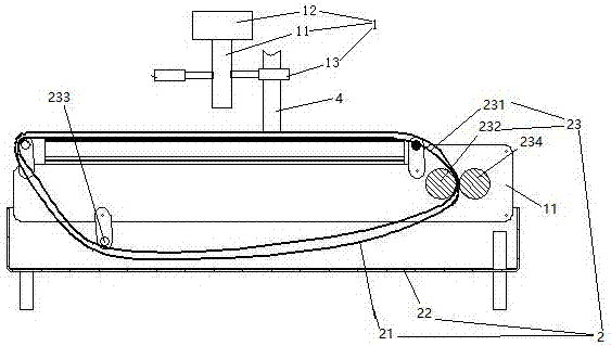
[0003] The invention provides a fluorescent lamp tube end face cleaning device for cleaning the powder accumulation at the tube opening with high cleaning efficiency, so as to solve the problem of low efficiency and laborious manual wiping of the powder accumulation at the tube opening

Method used


Image

  • Device for cleaning lamp tube end surfaces of fluorescent lamps
  • Device for cleaning lamp tube end surfaces of fluorescent lamps
  • Device for cleaning lamp tube end surfaces of fluorescent lamps

Examples


Embodiment 2

[0031] Embodiment two, the difference with embodiment one is:

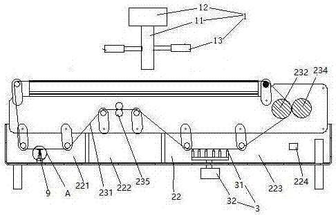
[0032] see figure 2 The water tank 22 is provided with a primary cleaning pool 221 , a sewage storage pool 222 and a secondary cleaning pool 223 in sequence along the moving direction of the conveyor belt 231 .

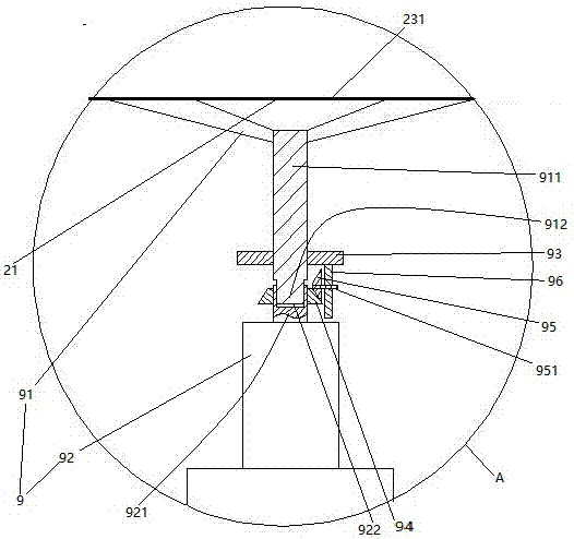
[0033] A dirt detachment booster mechanism 9 is provided in the primary cleaning tank 221 . A pair of second squeezing rollers 235 are arranged at the sewage storage tank 222 . The secondary cleaning tank 223 is provided with a pair of light-transmitting windows 224 distributed on two opposite side walls of the secondary cleaning tank.

[0034] see image 3 Dirt breaks away from booster mechanism 9 and packs blade 91 and rotary motor 92. The rotating shaft 911 of the blade is provided with a spline connection head 912 and a support plate 93 above the spline connection head. The rotating shaft 911 of the blade extends in the vertical direction. The end surface of the power output shaft 921 of the ro...

Embodiment 3

[0047] Embodiment three, the difference with embodiment two is:

[0048] see Figure 6 , one end of the heat conduction sleeve 734 and one end of the heat sink 71 are sealed against the sealing plate 74 , that is, both the heat conduction sleeve and the heat sink can slide relative to the seal plate 74 . The other end of the heat conducting sleeve 734 and the other end of the radiator 71 are sealed and connected together through the annular liquid storage bag 75 . The annular liquid storage bag 75 is filled with heat-insulating liquid, and the heat-insulating liquid makes the annular liquid storage bag 75 in an elastically expanded state. When the temperature is below 25° C., a sealed cavity 76 is formed among the heat conducting sleeve 734 , the sealing plate 74 , the radiator 71 and the annular liquid storage bag 75 . The sealed cavity 76 communicates with the annular liquid storage bag 75 .

[0049] When in use, the annular liquid storage bag 75 is positioned above the s...


PUM


Abstract

The invention relates to equipment for producing lamp tubes of fluorescent lamps, in particular to a device for cleaning the lamp tube end surfaces of fluorescent lamps. The device comprises a lamp tube fixing mechanism and a tube opening wiping mechanism, wherein the lamp tube fixing mechanism comprises a vertical shaft, a shifting motor for driving the vertical shaft to rotate and tube chucks which are distributed in the axial direction of a rotating shaft and connected with the vertical shaft and can keep lamp tubes in a vertical state; the tube opening wiping mechanism comprises a wiping object, a water tank and a driving mechanism; and the driving mechanism is used for driving the wiping object to carry out circulating motion of going below one of the tube chucks and across the water tank. The device for cleaning the lamp tube end surfaces of the fluorescent lamps, which is provided by the invention, is high in cleaning efficiency and is used for cleaning dust deposits in tube openings so as to solve the problem that the manual wiping of the dust deposits in the tube openings is low in efficiency and wastes labor.

Description

technical field [0001] The invention relates to equipment for producing fluorescent lamp tubes, in particular to a device for cleaning the end faces of fluorescent lamp tubes. Background technique [0002] During the production process of the fluorescent lamp tube, it is necessary to remove the phosphor powder (commonly known as tube mouth powder) coated on the end of the tube to prevent the tube mouth powder from falling off into the tube and causing dirty tubes. The existing method for removing the powder accumulation at the mouth of the nozzle is to manually wipe with a rag, so the efficiency is low. Contents of the invention [0003] The invention provides a fluorescent lamp tube end face cleaning device with high cleaning efficiency for cleaning the powder accumulation at the tube mouth, so as to solve the problem of low efficiency and laborious manual wiping of the powder accumulation at the tube mouth. [0004] The above technical problems are solved by the followi...

Claims


Application Information

Patent Timeline
Patent Type & Authority Applications(China)
IPC IPC(8): B08B1/02G01N21/59B08B1/20
CPCG01N21/59B08B13/00B08B1/50B08B1/20B08B1/143B08B1/30
Inventor 危金兰
Owner 台州市印务有限公司
Learn More