
Electronic component auxiliary mounting structure

A technology for mounting structures and electronic components, applied in electrical components, electrical components, etc., can solve problems such as low work efficiency, narrow application range, circuit board damage, etc., to achieve the effect of improving convenience and improving work efficiency

Active Publication Date: 2021-11-23
NANTONG HONGJINBEI ELECTRONICS TECH CO LTD
View PDF5 Cites 0 Cited by
  • Summary
  • Abstract
  • Description
  • Claims
  • Application Information

AI Technical Summary

Problems solved by technology

[0003] For example, a multi-functional auxiliary mounting table for electronic component processing in Patent No. CN202011098168.2, although the device can clamp and rotate electronic components, it only functions as a mechanical arm, and the device is in the process of actual use , cannot cooperate with the conveyor belt to process circuit boards at multiple positions, and the device cannot automatically load and blank circuit boards at multiple positions at the same time during the auxiliary installation of electronic components, and the work efficiency is low;
[0004] The existing auxiliary installation equipment for electronic components cannot adapt to circuit boards of different sizes during use, and it is difficult to perform adaptive adjustment work on multiple circuit boards of different sizes while installing electronic components. During the process of feeding and blanking the circuit board, it is easy to cause damage to the circuit board and does not have a protective function

Method used


Image

  • Electronic component auxiliary mounting structure
  • Electronic component auxiliary mounting structure
  • Electronic component auxiliary mounting structure

Examples


Embodiment

[0034]In order to make the purpose, technical solution and advantages of the present invention clearer, the following will further describe the implementation of the present invention in detail in conjunction with the accompanying drawings.

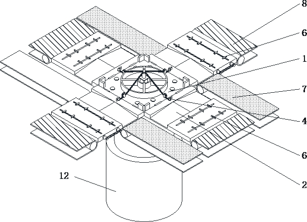
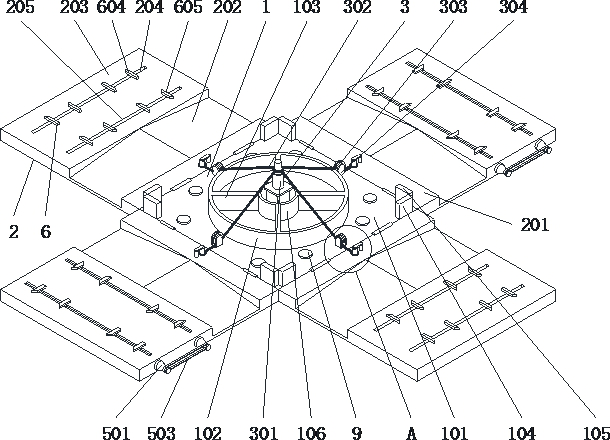
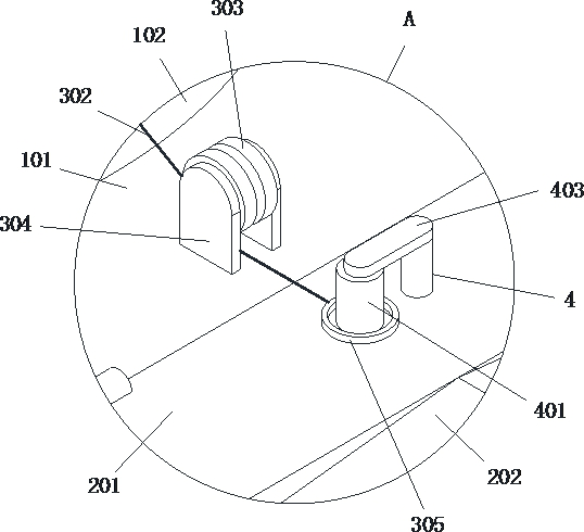
[0035] Such as Figure 1-7 As shown, an auxiliary installation structure for electronic components includes a support assembly 1, a discharge conveyor belt 7, a feed conveyor belt 8, a mechanical arm rocker shaft support 9 and an electric push rod 12, so as to adapt to the discharge conveyor belt 7 and the height of the feed conveyor belt 8 are used, and the surrounding rotation of the support assembly 1 is equipped with a feeding assembly 2. During the forward movement of the feed conveyor belt 8, the feeding assembly 2 enables the device to pass through the feed conveyor belt. 8 Squeeze the circuit board into the surface of the feeding assembly 2 of the device to facilitate subsequent automatic fixing of the circuit board. The bottom of...


PUM


Abstract

The invention belongs to the technical field of electronic components, and particularly relates to an electronic component auxiliary mounting structure which comprises a supporting assembly, discharging conveying belts, a feeding conveying belt, a mechanical arm rocker arm shaft support and an electric push rod, wherein feeding assemblies are rotatably mounted on the periphery of the supporting assembly, and the electric push rod is fixedly arranged at the bottom of the supporting assembly; a traction assembly is fixedly installed in the middle of the supporting assembly, the tail end of the traction assembly is connected with a buckle, the buckle is fixedly installed on the surface of the feeding assembly, a transmission assembly is installed in the feeding assembly, a clamping assembly is connected to the upper portion of the transmission assembly, discharging conveying belts are arranged on the left side and the right side of the feeding assembly, and the feeding conveying belt is arranged at the rear side of the feeding assembly. According to the device, the traction assembly and the clamping assembly are arranged, so that the device can be used in cooperation with the conveying belt, electronic elements are installed on a plurality of circuit boards at the same time, and follow-up automatic feeding and discharging are facilitated.

Description

technical field [0001] The invention relates to the technical field of electronic components, in particular to an auxiliary mounting structure for electronic components. Background technique [0002] In the process of using electrical equipment, circuit components are needed to control the switch and size of the current. Electronic components are the basic components of circuit components. In the process of installing electronic components, auxiliary installation equipment is required. Now There are still some defects in the use of some electronic component auxiliary installation equipment. [0003] For example, a multi-functional auxiliary mounting table for electronic component processing in Patent No. CN202011098168.2, although the device can clamp and rotate electronic components, it only functions as a mechanical arm, and the device is in the process of actual use , cannot cooperate with the conveyor belt to process circuit boards at multiple positions, and the device ...

Claims


Application Information

Patent Timeline
Patent Type & Authority Applications(China)
IPC IPC(8): H05K13/00H05K13/04
CPCH05K13/0061H05K13/0069H05K13/0404
Inventor 杨海林
Owner NANTONG HONGJINBEI ELECTRONICS TECH CO LTD
Learn More