
Michelson interference type fiber accelerometer

An acceleration sensor and interferometric technology, which is applied in the direction of measuring acceleration, speed/acceleration/shock measurement, instruments, etc., can solve the problems of low sensor sensitivity and poor repeatability, and achieve the effect of mature technology, convenient assembly and low correlation

Pending Publication Date: 2017-07-11
CHINA THREE GORGES UNIV
View PDF13 Cites 29 Cited by
  • Summary
  • Abstract
  • Description
  • Claims
  • Application Information

AI Technical Summary

Problems solved by technology

However, although the patents "A Fiber Optic Accelerometer" (Application No.: 201510519101.4) and "A Vertical Vibration Displacement Sensor Based on Michelson Interferometer" (Application No.: 201310018899.5) use interferometric phase sensing technology to detect acceleration or displacement, but The mechanical structure is still required as a sensitive element, the sensitivity of the sensor is not high, and the repeatability is poor

Method used


Image

  • Michelson interference type fiber accelerometer
  • Michelson interference type fiber accelerometer
  • Michelson interference type fiber accelerometer

Examples


Embodiment Construction

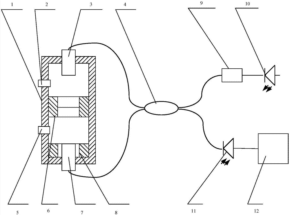
[0025] Such as figure 1 , figure 2 As shown, a Michelson interferometric fiber optic acceleration sensor includes a cylinder 1, an upper limit pin 2, a first collimator 3, an optical coupler 4, a lower limit pin 5, a mass 6, and a second collimator 7 , Ring magnet 8.

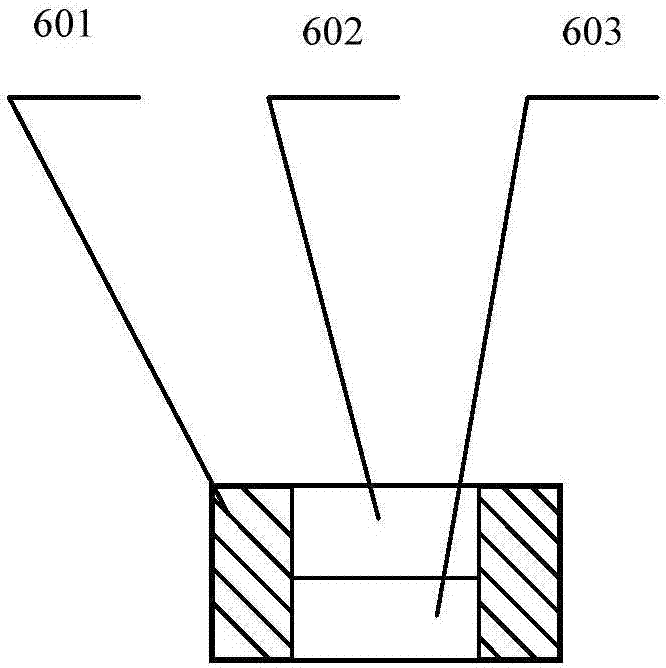
[0026] The first collimator 3 is fixedly installed directly above the cylinder 1, and the second collimator 7 is fixedly installed directly below. have equal distances. The proof mass 6 is used to adjust the sensitivity and resonance frequency of the acceleration sensor, reflect the incident light from the first collimator 3 and the second collimator 7, and rotate the polarization state of the light by 90° clockwise.

[0027] The first collimator 3 and the second collimator 7 are connected to the optical coupler 4, and the optical coupler 4, the first collimator 3, the upper reflection surface of the proof mass 6 and the free space optical path between the two constitute the first A Michelson interference a...


PUM


Abstract

A Michelson interference type fiber accelerometer comprises a cylinder body, an upper limit pin, a first collimator, an optical coupler, a lower limit pin, a mass block, a second collimator, and an annular magnet; the accelerometer also comprises an optical isolator, a laser light source, a photoelectric detector and a phase demodulation circuit; the mass block is designed as a part of a Michelson interferormeter free space optical path, and is suspended by using a static magnetic repulsion magnetic flux effect, thus converting external acceleration changes into minimal displacement of the mass block; the differential fiber Michelson interferormeter can detect the phase changes caused by the mass block displacements, thus real time demodulating the sensor acceleration changes; the accelerometer uses the magnetic suspension mode to avoid the machinery damping influences, and imports a bireflection Faraday optical rotation structure to eliminate the subordinate fading influences; the Michelson interference type fiber accelerometer is high in sensitivity, good in stability, small in size, simple in making, and has good application prospects.

Description

technical field [0001] The invention relates to an acceleration sensor, in particular to a Michelson interference optical fiber acceleration sensor. Background technique [0002] Compared with conventional acceleration sensors, optical fiber acceleration sensors have obvious advantages in sensitivity, dynamic range, reliability, etc., and are widely used in national defense, military and other fields. At present, most fiber optic acceleration sensors use elastic elements and mass blocks to convert external acceleration into displacement or strain, and then transmit the displacement or strain to the sensing fiber to change the optical wavelength, phase and other parameters of the signal in the sensing fiber. , by demodulating the change of optical parameters to obtain the acceleration of the outside world. For example, the patents "A Cantilever Beam Type Fiber Bragg Grating Accelerometer" (Application No.: 200710065321.X), "Fiber Bragg Grating Accelerometer Based on Cantilev...

Claims


Application Information

Patent Timeline
IPC IPC(8): G01P15/093
CPCG01P15/093
Inventor 罗志会陈思王凤钧陈小刚潘礼庆杨先卫肖焱山王习东
Owner CHINA THREE GORGES UNIV
Learn More