
Automobile headlamp based on laser excitation of fluorescence optical fiber

A technology for exciting fluorescence and fluorescent optical fibers, which is applied to optical components used to change the spectral characteristics of emitted light, headlights, and semiconductor devices for light-emitting components. , to achieve the effects of compact structure, easy access to laser modules, and good heat dissipation

Inactive Publication Date: 2017-07-11
SHANGHAI INST OF OPTICS & FINE MECHANICS CHINESE ACAD OF SCI
View PDF5 Cites 15 Cited by
  • Summary
  • Abstract
  • Description
  • Claims
  • Application Information

AI Technical Summary

Problems solved by technology

However, due to this structure, the laser light emitted by the laser module cannot be well coupled with the fluorescent sheet, resulting in uneven light emission, and it is not easy to make a compact structure by using a reflector.

Method used


Image

  • Automobile headlamp based on laser excitation of fluorescence optical fiber
  • Automobile headlamp based on laser excitation of fluorescence optical fiber

Examples


Embodiment 1

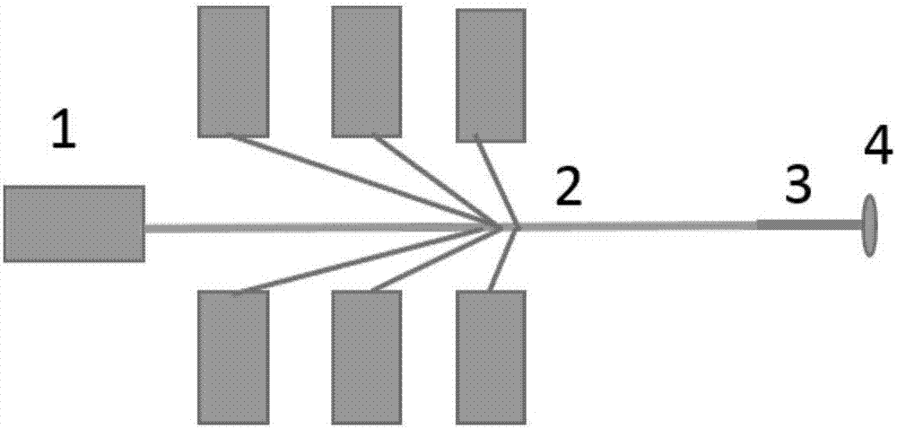
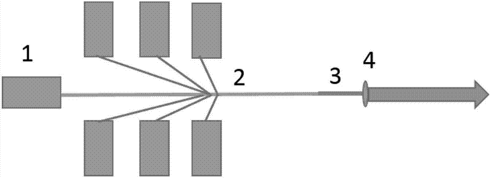
[0024] figure 1 A schematic diagram of the structure of a laser-excited fluorescent fiber optic automotive headlight is given, as shown in figure 1 shown. Including: a laser module 1, used to emit laser light; an optical fiber 2, connected to the laser module 1, used to transmit the laser light emitted by the laser module 1; a fluorescent optical fiber 3, connected to the optical fiber 2; specifically , in this embodiment, after the laser module 1 emits laser light, the laser light is transmitted to the fluorescent optical fiber 3 through the optical fiber 2, and the laser light will excite the fluorescent optical fiber to generate a white light beam visible to human eyes. The white light beam is expanded through the lens 4 at the end of the optical fiber to generate parallel light, which results in a smaller emission angle, thereby increasing the overall irradiation distance of the vehicle light.

[0025] figure 2 A schematic diagram of the use state of a fiber-optic lase...

Embodiment 2

[0028] In this embodiment, multiple lasers are arranged in the laser module 1, and the laser light emitted by the lasers is coupled through the optical fiber 2, so as to increase the power of the laser. As the power of the laser is increased, the power of the laser injected into the fluorescent optical fiber 3 is also increased, and the power of the light in the red, yellow and green segments generated by the laser irradiation is also enhanced, and the power of the formed white light beam is also enhanced. The white light beam is expanded through the lens 4 at the end of the fluorescent optical fiber 3 to generate parallel light, which obtains a smaller emission angle and realizes the purpose of remote irradiation of vehicle lights.

[0029] Tests have shown that the laser-excited fluorescent optical fiber automotive headlight of the present invention has a longer irradiation distance. Compared with traditional LED headlights, the light transmission of the car light proposed in...


PUM


Abstract

An automobile headlamp based on laser excitation of a fluorescence optical fiber comprises a laser module, an optical fiber and the fluorescence optical fiber, wherein the laser module is used for emitting a laser; the optical fiber is connected with the laser module and used for transmitting the laser emitted by the laser module; and one end of the fluorescence optical fiber is connected with the optical fiber, and a lens is processed on the other end surface of the fluorescence optical fiber. According to the automobile headlamp based on laser excitation of the fluorescence optical fiber, the design of the automobile headlamp is greatly simplified; the structure is compact; the laser module is easy to replace; through connection of the optical fiber, the laser module can be placed in places outside the automobile headlamp, so that a better heat dissipation effect is achieved; and in addition, the automobile headlamp has a farther irradiation distance.

Description

technical field [0001] The invention relates to the field of automobile lamp lighting, in particular to an automobile headlight based on a laser-excited fluorescent optical fiber. Background technique [0002] Laser headlights have been called the "reasonable next step" after LED headlights, which are more energy-efficient and more fuel-efficient. The principle is that the blue light of the laser light-emitting diode will penetrate the fluorescent material in the headlight unit and convert it into a diffused white light, which is bright and more friendly to the eyes. [0003] The advantages of laser headlights over traditional LED headlights are obvious. The luminous intensity of traditional LED headlights is 100 lumens per watt, and the irradiation distance is about 300 meters; while laser headlights reach 170 lumens per watt, and the irradiation distance is 500-600 meters. meters, so that the driver can know the road conditions ahead in advance. The light source of laser...

Claims


Application Information

Patent Timeline
Patent Type & Authority Applications(China)
IPC IPC(8): F21S8/10F21V8/00F21V9/10F21W101/02F21W101/10F21Y115/30F21V9/40F21W107/10
CPCF21S41/14F21S41/24F21S41/285F21W2102/00F21W2107/10
Inventor 姜本学陈水林张龙
Owner SHANGHAI INST OF OPTICS & FINE MECHANICS CHINESE ACAD OF SCI
Learn More