Laser processing system and method
A laser processing method and laser processing technology, which are applied in metal processing, laser welding equipment, metal processing equipment, etc., can solve the problems of reduced laser energy utilization rate, high cost, and reduced effect of picosecond-level laser pulse adjustment.
- Summary
- Abstract
- Description
- Claims
- Application Information
AI Technical Summary
Problems solved by technology
Method used
Image
Examples
Embodiment 1
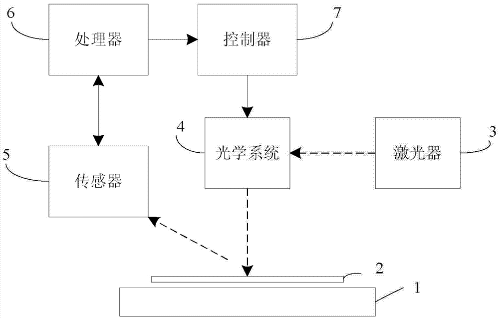
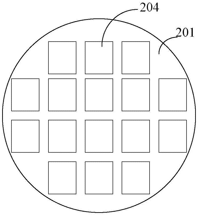
[0034] Such as Figure 1-3 As shown, a laser processing system of the present invention is used to process (i.e. cut) the workpiece material 2 on the workpiece table 1, including: a laser 3, which provides the laser 301 required for processing. Preferably, the laser 3 is Pulse laser, the width of its pulse is not limited, such as the laser 3 with ultrashort pulse width, which is beneficial to control the thermal influence in the cutting process; the optical system 4 is located above the workpiece table 1, and adjusts the laser 301, and project the adjusted laser 301 spot onto the workpiece table 1; the sensor 5 is arranged above the workpiece table 1, and collects the parameter information of the workpiece material 2; the processor 6 communicates with the workpiece table 1. The sensor 5 is connected to receive and process the parameter information collected by the sensor 5 to obtain the spot size of the laser 301 required by the workpiece material 2; the controller 7 is connec...
Embodiment 2
[0045] The difference from Embodiment 1 is that in Embodiment 2, the optical system 4 includes a turntable mechanism 403, and the turntable mechanism 403 is provided with a number of through holes, and the number of the through holes is 3-5. In the example, there are 4 through holes, and diffractive optical elements are arranged in the through holes, and the shapes of the diffractive optical elements in the 4 through holes are different, and the spot shape obtained by the laser 301 through different diffractive optical elements and different sizes, such as Figure 4a As shown, 404a-404d are different diffractive optical elements installed on the turntable mechanism 403. When the laser light 301 is incident on the diffractive optical element, different diffractive spots 405a-405d will be formed, as shown in Figure 4b As shown, 405a is an elliptical spot formed by 404a with a major axis l1 and a minor axis m2. Assuming that the laser pulse energy is u, the corresponding laser p...
Embodiment 3
[0047] Different from Embodiment 1, in this embodiment, the sensor 5 is a laser displacement sensor, which measures the thickness of the workpiece material 2 and the remaining thickness of the material after cutting, so as to obtain the cutting depth of the workpiece material 2, and the processor 6 Adjust the laser pulse energy density according to the change of cutting depth to adjust the cutting depth, among which reducing the spot area can increase the laser energy pulse density to obtain a greater depth of cut, increasing the spot area can reduce the laser energy pulse density to reduce the cutting depth , if the target cutting depth of the workpiece material 2 is L, and the processor 6 calculates the current cutting depth as L1, then the deviation ΔL=L1–L, at this time, the controller 7 runs the PID control algorithm to obtain the currently required spot The area is controlled by the controller 7 so that the actual depth of cut is consistent with the target depth of cut, a...
PUM
 Abstract
Description
Claims
Application Information
 - R&D
- Intellectual Property
- Life Sciences
- Materials
- Tech Scout
- Unparalleled Data Quality
- Higher Quality Content
- 60% Fewer Hallucinations
Browse by: Latest US Patents, China's latest patents, Technical Efficacy Thesaurus, Application Domain, Technology Topic, Popular Technical Reports.
© 2025 PatSnap. All rights reserved.Legal|Privacy policy|Modern Slavery Act Transparency Statement|Sitemap|About US| Contact US: help@patsnap.com


