
A led power supply with protection circuit

A technology of LED power supply and protection circuit, which is applied in the direction of electric light source, electroluminescence light source, light source, etc., and can solve problems such as difficulty for users, large inrush current, uncontrollable inrush current, etc.

Active Publication Date: 2019-05-03
SELF ELECTRONICS CO LTD
View PDF8 Cites 0 Cited by
  • Summary
  • Abstract
  • Description
  • Claims
  • Application Information

AI Technical Summary

Problems solved by technology

However, in the LED switching power supply, there is usually a large inrush current when the lamp is turned on, and sometimes even the front-end air switch triggers protection, causing the power grid to trip
Therefore, the method of series thermistor is usually used to limit the inrush current, but the inrush current is uncontrollable
It is difficult for users to choose the right thermistor to prevent grid tripping under an uncontrollable surge current

Method used


Image

  • A led power supply with protection circuit
  • A led power supply with protection circuit
  • A led power supply with protection circuit

Examples


Embodiment Construction

[0010] Specific embodiments of the present invention will be described in further detail below based on the accompanying drawings. It should be understood that the description of the embodiments of the present invention here is not intended to limit the protection scope of the present invention.

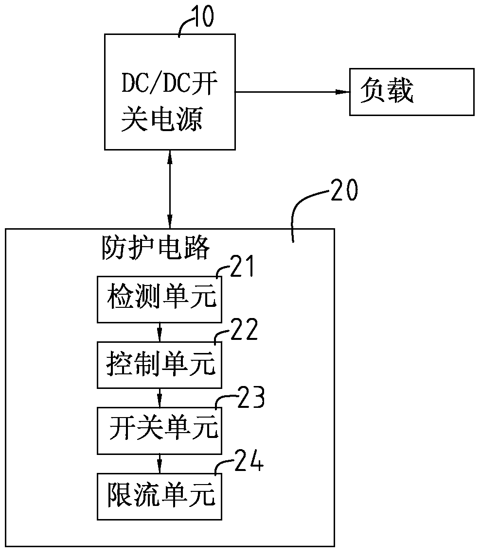
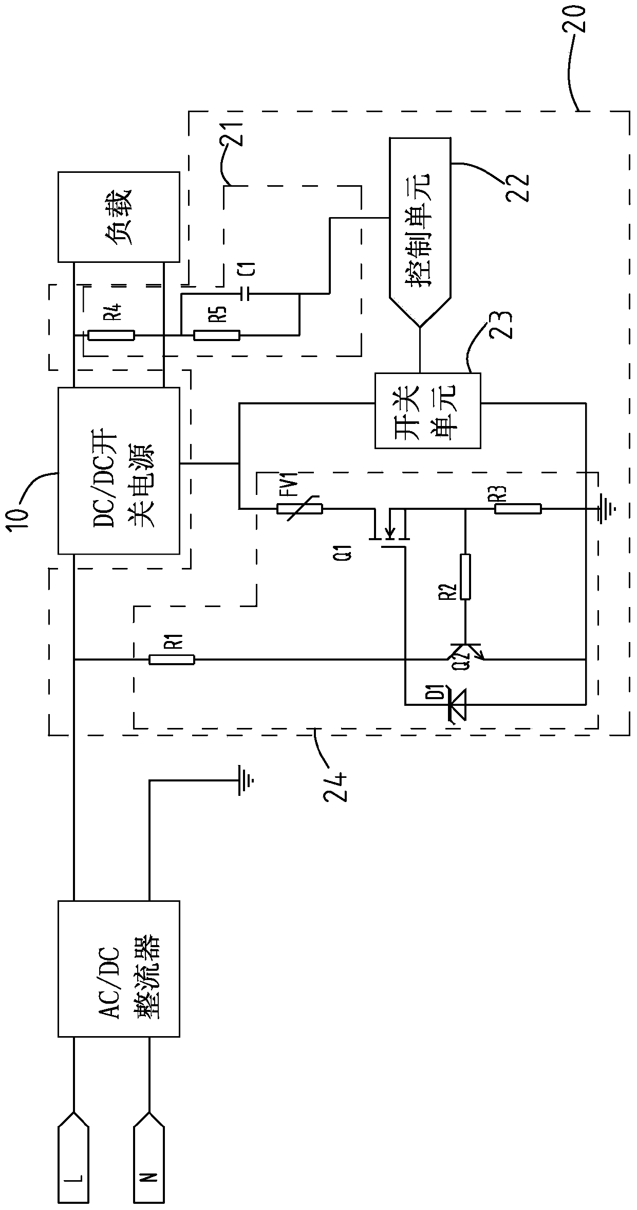
[0011] see figure 1 and figure 2 , which is a functional block diagram of an LED power supply 100 with a protection circuit provided by the present invention. The LED power supply 100 with protection circuit includes a DC / DC switching power supply 10 and a protection circuit 20 connected in series with the DC / DC switching power supply. As is well known, the LED power supply 100 also includes other functional modules, such as an AC / DC rectifier, and a load connected to the output end of the DC / DC switching power supply 10 . In the present invention, these functional modules are not regarded as the focus of the invention, and will not be repeated here.

[0012] The DC / DC switching...


PUM


Abstract

An LED power supply with a protection circuit, the LED power supply includes a DC / DC switching power supply, and the DC / DC switching power supply includes a capacitor. The LED power supply also includes a protection circuit. The protective power supply includes a detection unit for detecting the charging state of the capacitor, a control unit, a switch unit, and a current limiting unit. The current limiting unit is used to limit the magnitude of the current flowing through the capacitor. When the detection unit detects that the capacitor is full, it sends a control signal to the control unit, and the control unit controls the switch unit to turn on after receiving the control signal, so that the LED power supply with the protection circuit enters normal operation state. Because the LED power supply with protection circuit has the current limiting unit, and the current limiting unit can limit the inrush current to a very small value in the early stage when the LED power supply is turned on under the cooperation of the detection unit and the control unit. Below, so that it can meet the more harsh use environment.

Description

technical field [0001] The invention relates to lighting system equipment, in particular to an LED power supply with a protection circuit. Background technique [0002] In general daily life, various lighting devices can be seen everywhere, for example, fluorescent lamps, street lamps, table lamps, art lamps and the like. Among the above-mentioned lighting devices, traditionally most of them use tungsten filament bulbs as light sources. In recent years, light-emitting diodes (LEDs) have been used as a source of light due to advances in technology. What's more, in addition to lighting equipment, for general traffic signs, billboards, car lights, etc., light-emitting diodes are also used as light-emitting light sources instead. As mentioned above, the advantage of using light-emitting diodes as a light source is that it saves power and has higher brightness, so it has gradually become popular in use. [0003] With the popularization of LED lamps, LED lamps are used in more ...

Claims


Application Information

Patent Timeline
Patent Type & Authority Patents(China)
IPC IPC(8): H05B33/08H05B44/00
CPCH05B45/00Y02B20/30
Inventor 王俊应文
Owner SELF ELECTRONICS CO LTD
Learn More