Antenna unit, mimo antenna and terminal

An antenna unit and antenna technology, applied in the field of communication, can solve the problems of low correlation coefficient, narrow space and small distance of the antenna unit, and achieve the effect of miniaturization and size reduction

Active Publication Date: 2020-04-14
HUAWEI TECH CO LTD
View PDF4 Cites 0 Cited by
  • Summary
  • Abstract
  • Description
  • Claims
  • Application Information

AI Technical Summary

Problems solved by technology

[0003] However, when a multiple-input multiple-output (MIMO, Multiple-Input Multiple-Output) antenna system is applied to a base station, due to the large available space of the base station, the application of multi-antenna technology is easy to implement. For increasingly miniaturized terminal equipment , multiple antennas need to be concentrated in a small space. In order to obtain good performance, these antenna elements need to have good isolation, and at the same time, there must be a low correlation coefficient between the antenna elements; moreover, there are currently multiple Standards to meet different applications, the frequency bands covered by these standards are different, so the antenna system is required to be able to achieve multi-band work; in handheld devices (such as mobile phones), the space is very small, the antenna elements that make up the MIMO antenna The distances are small, and it is very difficult to design a MIMO antenna system that meets these requirements and performs well

Method used


Image

  • Antenna unit, mimo antenna and terminal
  • Antenna unit, mimo antenna and terminal
  • Antenna unit, mimo antenna and terminal

Examples


Embodiment 1

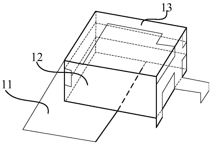
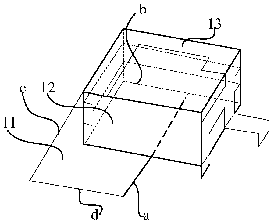
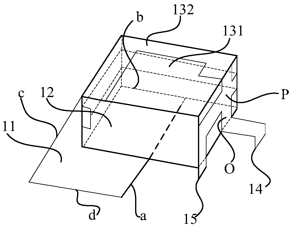
[0273] Will 8 such as Figure 4 The antenna unit structure shown in the Figure 17 The manner shown is placed on the ground plane 100, wherein, in each antenna unit, see Figure 4 , the projection of the second side of the support 12 on the horizontal plane falls on the straight line where the second side b of the clearance area 11 is located, and coincides with at least a part of the second side b of the clearance area 11, the support The distance between the projection of 12 on the horizontal plane and the third side c and the fourth side d of the clearance area 11 is 0-5 mm, and the first side of the bracket 12 is located outside the clearance area 11 .

Embodiment 2

[0275] Will 8 such as Figure 10 Antenna units shown with Figure 23 The manner shown is placed on the ground plane 100, wherein, in each antenna unit, see Figure 10 , the headroom area 11 includes a first area 111 and a second area 112 that are orthogonal to each other, the projection of the third side of the bracket 12 on the horizontal plane coincides with the side i of the first area 111, and the third side of the bracket 12 The projections of the two sides on the horizontal plane fall on the straight line where the side 4 o of the first area 111 is located, and partly coincide with the side 4 o of the first area 111, the projection of the support 12 on the horizontal plane and the first The distance between the side 2m of the area 111 and the side e of the second area 112 away from the first area 111 is 0-5mm, and the partial projection of the first side of the bracket 12 on the horizontal plane is located in the clear area 11 exterior.

experiment example

[0277] After performing the return loss and isolation test on the MIMO antenna in Embodiment 1, it is obtained as follows Figure 24 and Figure 25 The results shown.

[0278] Among them, see Figure 24 , S 11 and S 22 Respectively represent return loss S parameters of the first antenna unit 1 and the second antenna unit 2 in the 1.8-1.9GHz and 2.3-2.7GHz frequency bands. Depend on Figure 24 It can be known that the return loss S of the first antenna unit 1 and the second antenna unit 2 in the 1.8-1.9GHz frequency band 11 and S 22 Both are less than -10dB, the return loss S of the first antenna unit 1 in the frequency band of 2.3-2.7GHz 11 Less than -10dB, the return loss S of the second antenna unit 2 22 Less than -10dB. It shows that the MIMO antenna can not only receive signals from multiple directions at the same time in the 1.8-1.92GHz and 2.3-2.7GHz frequency bands, but also transmit signals to multiple directions at the same time, and can be widely used in mul...


PUM


Abstract

This patent application relates to the field of communication technology, and in particular to an antenna unit, MIMO antenna and terminal. The antenna unit can realize the miniaturization of the antenna unit while realizing the multi-band operation, and can reduce the size of the MIMO antenna when applied to the MIMO antenna, and can meet the requirements of the small size of the terminal when the MIMO antenna is applied to the terminal. design needs. An embodiment of the present patent application provides an antenna unit, the antenna unit includes: a clearance area, a support, and at least two branches; each branch is respectively arranged on the support; part of the projection of the support on the horizontal plane falls in the clearance area, and each The projection on the horizontal plane of one end of a stub used to connect the feed point is located outside the clear area, and the projection of the end on the horizontal plane is located inside the clear area.

Description

technical field [0001] This patent application relates to the field of communication technologies, and in particular to an antenna unit, a Multiple-Input Multiple-Output (MIMO, Multiple-Input Multiple-Output) antenna and a terminal. Background technique [0002] At present, the traditional single input single output (SISO, single input single output) antenna system is not enough to meet the large capacity, high speed and high reliability requirements of the new generation wireless communication system due to the limitation of Shannon capacity. The objective fact is that how to achieve higher spectrum utilization has become an urgent problem to be solved in the development of new technologies in the field of wireless communication; multiple-input multiple-output (MIMO, Multiple-Input Multiple-Output) antenna system can effectively The communication link is decomposed into many parallel sub-channels, which can greatly increase the channel capacity, break through the limitation...

Claims


Application Information

Patent Timeline
Patent Type & Authority Patents(China)
IPC IPC(8): H01Q1/36H01Q1/50H01Q5/10H01Q5/28H01Q5/378H01Q1/52H01Q21/00
CPCH01Q5/10H01Q5/28H01Q5/378H01Q1/36H01Q1/50H01Q1/521H01Q21/00H01Q1/243H01Q1/48H01Q9/42H01Q21/28H01Q21/30H01Q5/371H01Q1/246H01Q21/061
Inventor 文舸一王俊张明施学良
Owner HUAWEI TECH CO LTD
Why Eureka
Try Eureka