Antenna unit, MIMO (Multiple-Input Multiple-Output) antenna and terminal
An antenna unit and antenna technology, applied in the field of communication, can solve the problems of narrow space, low correlation coefficient of antenna units, small distance, etc., and achieve the effect of reducing size and realizing miniaturization
- Summary
- Abstract
- Description
- Claims
- Application Information
AI Technical Summary
Problems solved by technology
Method used
Image
Examples
Embodiment 1
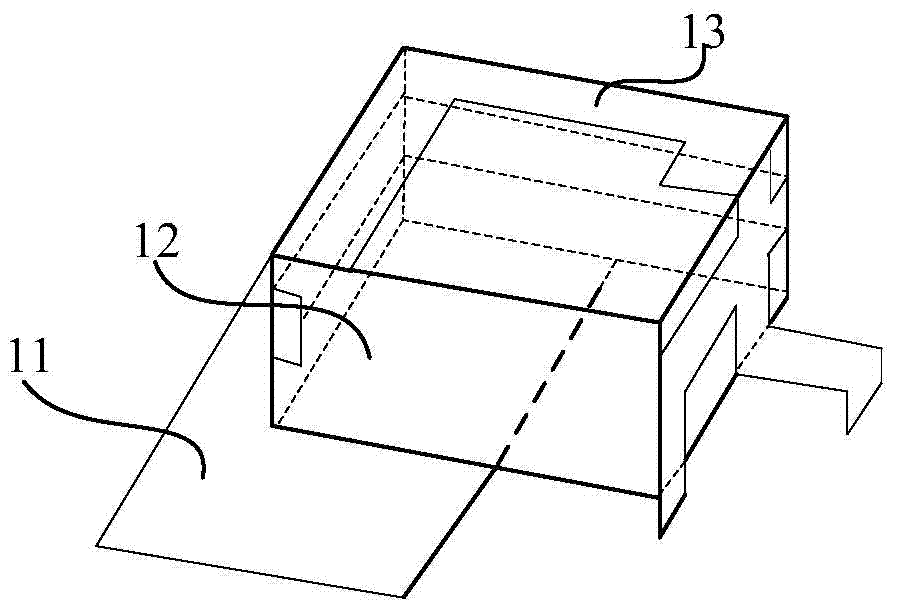
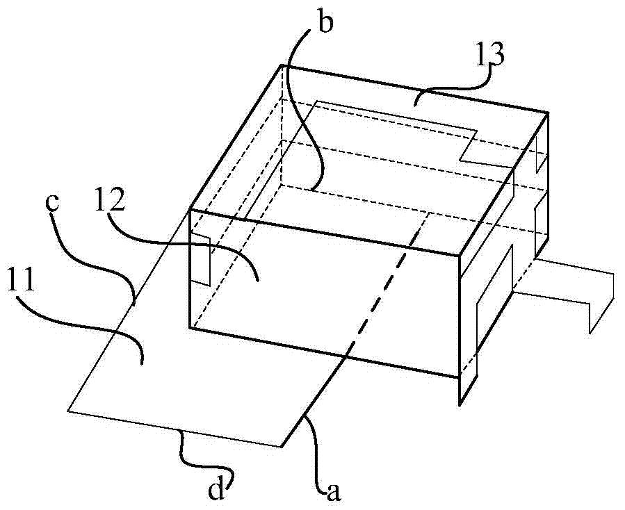
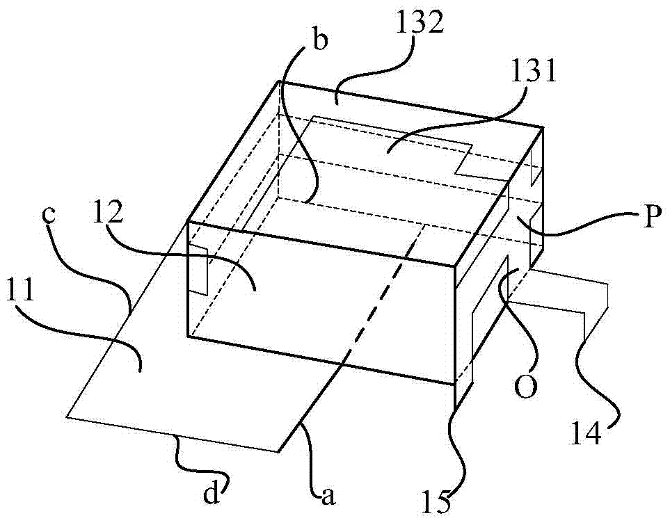
[0273] will be 8 as shown in the picture 4 The antenna unit structure shown in the picture 17 The manner shown is placed on the ground plane 100, wherein, in each antenna unit, see picture 4 , the projection of the second side of the support 12 on the horizontal plane falls on the straight line where the second side b of the clearance area 11 is located, and coincides with at least a part of the second side b of the clearance area 11, the support The distance between the projection of 12 on the horizontal plane and the third side c and the fourth side d of the clearance area 11 is 0-5 mm, and the first side of the bracket 12 is located outside the clearance area 11 .
Embodiment 2
[0275] will be 8 as shown in the picture 10 Antenna units shown with picture 23 The manner shown is placed on the ground plane 100, wherein, in each antenna unit, see picture 10 , the headroom area 11 includes a first area 111 and a second area 112 that are orthogonal to each other, the projection of the third side of the bracket 12 on the horizontal plane coincides with the side i of the first area 111, and the third side of the bracket 12 The projections of the two sides on the horizontal plane fall on the straight line where the side 4 o of the first area 111 is located, and partly coincide with the side 4 o of the first area 111, the projection of the support 12 on the horizontal plane and the first The distance between the side 2m of the area 111 and the side e of the second area 112 away from the first area 111 is 0-5mm, and the partial projection of the first side of the bracket 12 on the horizontal plane is located in the clear area 11 exterior.
experiment example
[0277] Obtained by performing return loss and isolation tests on the MIMO antenna in Example 1 as shown in the picture 24 and picture 25 The results shown.
[0278] Among them, see picture 24 , S 11 and S 22 Respectively represent return loss S parameters of the first antenna unit 1 and the second antenna unit 2 in the 1.8-1.9GHz and 2.3-2.7GHz frequency bands. Depend on picture 24 It can be known that the return loss S of the first antenna unit 1 and the second antenna unit 2 in the 1.8-1.9GHz frequency band 11 and S 22 Both are less than -10dB, the return loss S of the first antenna unit 1 in the frequency band of 2.3-2.7GHz 11 Less than -10dB, the return loss S of the second antenna unit 2 22 Less than -10dB. It shows that the MIMO antenna can not only receive signals from multiple directions at the same time in the 1.8-1.92GHz and 2.3-2.7GHz frequency bands, but also transmit signals to multiple directions at the same time, and can be widely used in multip...
PUM
 Abstract
Description
Claims
Application Information
 - R&D
- Intellectual Property
- Life Sciences
- Materials
- Tech Scout
- Unparalleled Data Quality
- Higher Quality Content
- 60% Fewer Hallucinations
Browse by: Latest US Patents, China's latest patents, Technical Efficacy Thesaurus, Application Domain, Technology Topic, Popular Technical Reports.
© 2025 PatSnap. All rights reserved.Legal|Privacy policy|Modern Slavery Act Transparency Statement|Sitemap|About US| Contact US: help@patsnap.com


