
A kind of cable support mechanism and cable platform

A technology of support mechanism and support line, which is applied in opto-mechanical equipment, microlithography exposure equipment, instruments, etc., can solve the problems of collision and friction between cables and the basic frame, cable stuck, unable to adapt to cables, etc. Control positioning accuracy, optimize support effect, and small sag effect

Active Publication Date: 2019-03-12
SHANGHAI MICRO ELECTRONICS EQUIP (GRP) CO LTD
View PDF4 Cites 0 Cited by
  • Summary
  • Abstract
  • Description
  • Claims
  • Application Information

AI Technical Summary

Problems solved by technology

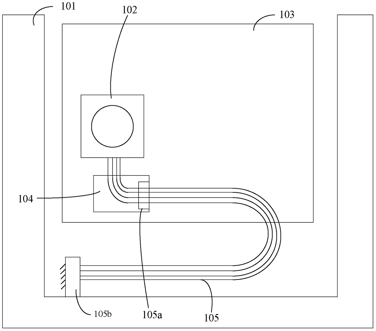
However, this solution has certain limitations. First of all, when there are too many cables, dividing the cables and tubes into two layers for clamping may make each layer too wide and increase the vertical space required for cables, which may easily lead to cable failure. The cable collides with the basic frame; secondly, the clamping position of the cable cannot be adjusted. In the actual cable support, since the position of the center of gravity is difficult to determine in advance, if the clamping position is inaccurate and cannot be adjusted, it will affect the control of the cable. The support effect is not good, and it cannot adapt to a variety of cables with different strokes; thirdly, in the actual movement process, it may be easy to get stuck with the cable due to the unreasonable length design of the connecting rod, thus affecting the movement of the cable table

Method used


Image

  • A kind of cable support mechanism and cable platform
  • A kind of cable support mechanism and cable platform
  • A kind of cable support mechanism and cable platform

Examples


Embodiment 1

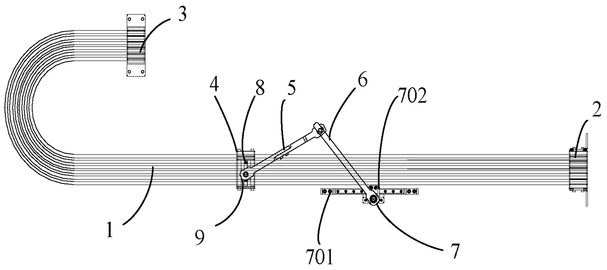
[0037] Such as Figure 2-5b As shown, the present invention provides a cable support mechanism for supporting the gravity of the U-shaped cable 1, the U-shaped cable 1 includes 3 layers of cables and 3 layers of pipes arranged in the horizontal direction, figure 2Every two lines form a layer of cables or pipes. One end of the U-shaped cable 1 is fixed on the basic frame (not shown in the figure) through the fixed end clamp 2, and the other end is connected to the cable platform through the movable end clamp 3. (not shown in the figure) is connected and moves together with the cable table.

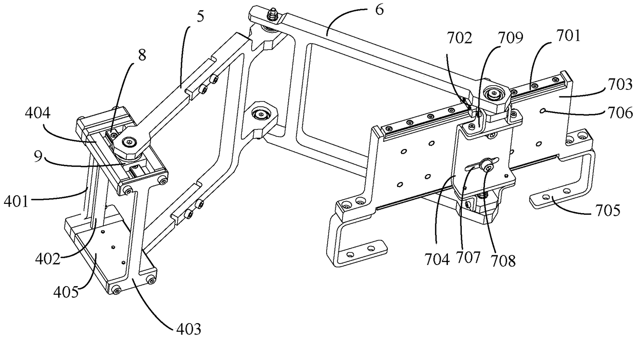
[0038] Please refer to figure 2 , the cable support mechanism includes a support clamp 4, a first link 5, a second link 6 and an adjustable connector 7, the U-shaped cable 1 passes through the support clamp 4, and the support clamp 4. Clamp the innermost layer of cables or tubes of the U-shaped cable, and only support the other 5 layers of cables or tubes. Since the movement trajectorie...

Embodiment 2

[0055] Such as Figure 6 As shown, different from Embodiment 1, in this embodiment, one end of one connecting rod in the first connecting rod 5 is connected to the top support plate 404, and one end of the other connecting rod is connected to the bottom The support plate 405 is connected, the first connecting rod 5 and the top support plate 404, the first connecting rod 5 and the bottom support plate 405 are all connected by a rotating pair, and the two connecting rods of the first connecting rod 5 The other end is provided with a first support rail 8, the first support rail 8 is affixed to the first connecting rod 5, and the first support slider 9 is slidably provided on the first support rail 8, and the first support slider 9 9 is connected with one end of the second connecting rod 6, and the first supporting slider 9 is connected with the second connecting rod 6 by a rotary pair. Adopting the above setting method can save the installation space of the cable support mechani...


PUM


Abstract

The invention discloses a cable supporting mechanism and a cable table. The cable supporting mechanism comprises a plurality of layers of flat cables and / or a plurality of layers of tube banks, wherein the cable supporting mechanism comprises a supporting cable clamp, a first connecting rod, a second connecting rod and an adjustable connecting piece, U-shaped cables pass trough the supporting cable clamp, and the supporting cable clamp is used for clamping the innermost layer of flat cables or tube banks in the U-shaped cables; two ends of the first connecting rod are connected to the supporting cable clamp and one end of the second connecting rod respectively, and the other end of the second connecting rod is movably connected with the adjustable connecting piece. The innermost layer of flat cables or tube banks is clamped by the supporting cable clamp, so that the U-shaped cables are effectively prevented from drooping, and collision friction is prevented from occurring with a foundation framework or other components; the supporting effect is further optimized by adjusting the positions of the supporting cable clamp and the U-shaped cables, so that the drooping quantity of the U-shaped cables is minimum; and moreover, the position of the second connecting rod is adjusted by the adjustable connecting piece, the supporting cable clamp is guaranteed to be smoother and more steady in the moving process along with the U-shaped cables, and the influence on a workpiece table is reduced.

Description

technical field [0001] The invention relates to a photolithography device, and specifically designs a cable support mechanism and a cable table. Background technique [0002] With the continuous improvement of the integration of large-scale integrated circuit devices and the continuous enhancement of lithography resolution, the requirements for the characteristic line width of lithography machines are also constantly increasing. Therefore, the requirements for the speed, acceleration and accuracy of the workpiece table are also increasing. keep improving. [0003] The operation of the workpiece table needs to be equipped with a motor drive system, an air flotation guidance system, a sensor detection system, etc., and a large number of signal lines, power lines, air pipes, water pipes, etc. are required to realize functions such as power supply, air supply, cooling, and control. During the movement of the workpiece table, these cables and pipelines will reciprocate synchrono...

Claims


Application Information

Patent Timeline
Patent Type & Authority Patents(China)
IPC IPC(8): G03F7/20
CPCG03F7/20G03F7/70808
Inventor 刘屈武李志龙
Owner SHANGHAI MICRO ELECTRONICS EQUIP (GRP) CO LTD
Learn More