
Display device

A display device and detection circuit technology, applied in static indicators, optics, instruments, etc., can solve problems such as weak anti-noise and static electricity, reduced production efficiency, and larger flexible wiring substrates, and achieve efficient calibration.

Active Publication Date: 2017-07-07
JAPAN DISPLAY INC
View PDF11 Cites 0 Cited by
  • Summary
  • Abstract
  • Description
  • Claims
  • Application Information

AI Technical Summary

Problems solved by technology

[0013] The detection of adjacent short-circuit faults between two detection electrodes adjacent to each other can be carried out by dot inspection for each intersection point of the scanning electrode and the detection electrode, but since the inspection takes time, the production efficiency is significantly reduced
In addition, the method of setting test points for the wiring connected to the detection electrode on the flexible wiring substrate to perform the open-short circuit test has disadvantages such as weak anti-noise and static electricity, or the flexible wiring substrate becomes larger.

Method used


Image

  • Display device
  • Display device
  • Display device

Examples


Embodiment Construction

[0073] Hereinafter, embodiments of the present invention will be specifically described with reference to the drawings.

[0074] In addition, in all the drawings for explaining the embodiments, elements having the same functions are assigned the same reference numerals, and redundant descriptions are omitted. In addition, the following examples are not intended to limit the interpretation of the claims of the present invention.

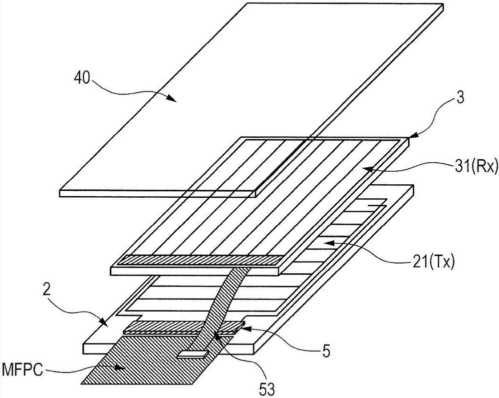
[0075] Figure 1A It is an exploded perspective view showing a schematic configuration of an example of an all-in-one liquid crystal display device including a touch panel built in a liquid crystal display panel.

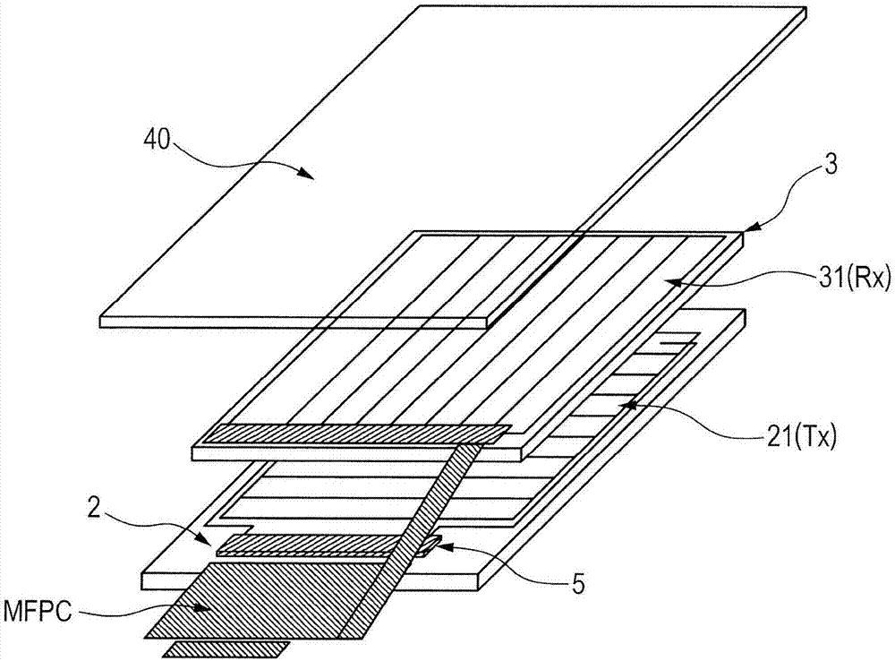
[0076] Figure 1B It is an exploded perspective view showing a schematic configuration of another example of an integrated liquid crystal display device incorporating a touch panel inside a liquid crystal display panel.

[0077] In order to reduce costs, Figure 1B The all-in-one LCD display unit shown will Figure 1A The shown main flex...


PUM


Abstract

The present invention provides a display device, which has an embedded touch panel function and is capable of executing calibration of cross capacitance efficiently. The liquid crystal display device with a plurality of pixels arranged in a matrix includes a first substrate, a second substrate, a liquid crystal interposed between the first and the second substrates, and a detection circuit. The second substrate includes a detection electrode for a touch panel. The respective pixels have pixel electrodes and counter electrodes. The counter electrode divided into a plurality of blocks is provided common to the respective pixels on a plurality of consecutive display lines. The counter electrode divided into blocks serves as the scanning electrode for the touch panel. The detection circuit includes a calibration capacity element provided for each of the detection electrodes, having one end connected to the detection electrode, and supplies a calibration voltage to the other end of the calibration capacity element in a touched position detection process.

Description

[0001] This application is a divisional application of an invention patent application with an application date of December 05, 2013, an application number of 201310652179.4, and an invention title of "liquid crystal display device". technical field [0002] The present invention relates to a liquid crystal display device, and particularly relates to an effective technology applied to an in-cell liquid crystal display device incorporating a touch panel. Background technique [0003] A display device with a device (hereinafter also referred to as a touch sensor or touch panel) for inputting information by performing a touch operation (contact pressing operation, hereinafter referred to as touch) on a display screen with a user's finger or a pen, etc. is used in a PDA or a mobile phone. Mobile electronic devices such as terminals, various home appliances, automated teller machines, etc. [0004] As such a touch panel, there is known a capacitive method that detects a change in...

Claims


Application Information

Patent Timeline
Patent Type & Authority Applications(China)
IPC IPC(8): G02F1/1333G06F3/041G09G3/36
CPCG02F1/13338G06F3/0412G06F3/0414G06F3/0418G09G3/3655G09G2354/00G02F1/134318G02F1/136254G06F3/04184G06F3/0443G06F3/0446G02F1/133G06F3/041G09G3/36G02F1/1309G02F1/133528G02F1/134309G02F1/136286G02F1/1368G02F2202/28G06F2203/04102G02F1/133302
Inventor 时田雅弘高畑昌志
Owner JAPAN DISPLAY INC
Learn More