
High-precision mirror surface automatic detection equipment and working method thereof

An automatic detection, high-precision technology, applied in the direction of cleaning methods using tools, cleaning methods using gas flow, chemical instruments and methods, etc., can solve the problems of increasing capital and labor costs, affecting life, mirror damage, etc., and achieve practical savings and manpower, improve accuracy, improve the effect of accuracy

Pending Publication Date: 2017-07-07
SUZHOU XINHE MIRRORS CO LTD
View PDF5 Cites 3 Cited by
  • Summary
  • Abstract
  • Description
  • Claims
  • Application Information

AI Technical Summary

Problems solved by technology

[0003] Most of the existing mirror inspection equipment adopts bare inspection. During the inspection process, a lot of dust will fall on the mirror or inspection equipment, which will cause serious pollution to the mirror and inspection equipment. , which will not only affect the cleanliness of the mirror surface, but also affect the accuracy of its test results, and will also cause pollution to the electrical components in the test equipment, affecting its service life; at the same time, due to the test environment The cleanliness of the mirror surface is poor, so after the mirror surface inspection, it is necessary to carry out subsequent dust removal treatment, which will not only increase the capital and labor costs of its production, but also cause damage to the mirror surface itself, so the existing mirror surface inspection equipment has yet to be completed. for improvement

Method used


Image

  • High-precision mirror surface automatic detection equipment and working method thereof
  • High-precision mirror surface automatic detection equipment and working method thereof
  • High-precision mirror surface automatic detection equipment and working method thereof

Examples


Embodiment 1

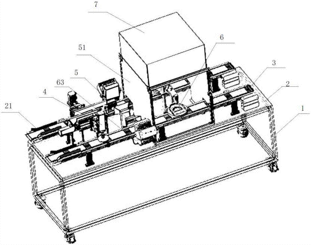
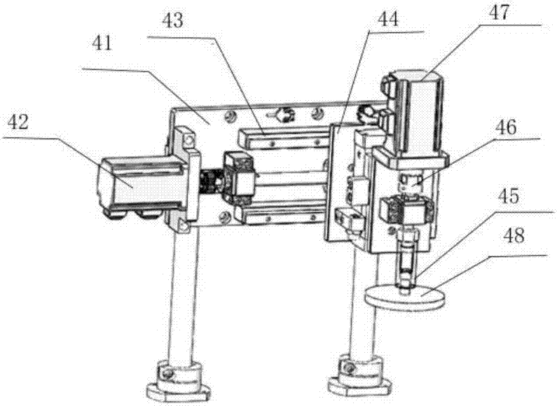
[0059] Such as Figure 1 to Figure 4 , Figure 9 , 10 A high-precision mirror automatic detection device shown includes: a body 1, a workbench 2, a dust removal device 4, a fan 5, a detection device 6 and a control device;

[0060] The relationship between the above components is as follows:

[0061] The workbench 2 is provided with a detection streamline 3, and the front and rear of the detection streamline 3 are respectively provided with a feed inlet and a discharge port, and a first station 31 and a second station 31 are arranged on the streamline. 32 and the third station 33; the dust removal device 4 is arranged on the first station 31, the fan 5 is arranged on the second station 32, the detection device 6 is arranged on the third station 33, and An air cleaner 7 is arranged above the detection device 6, and the dust removal device 4, the fan 5, the detection device 6 and the air cleaner 7 are all connected to the control device.

[0062] In this embodiment, the dust...

Embodiment 2

[0076] Such as Figure 5-8 as well as Figure 11 , 12 A high-precision mirror automatic detection device shown includes: a body 1, a workbench 2, a dust removal device 4, a fan 5, a detection device 6, a cleaning mechanism 8 and a control device;

[0077] The relationship between the above components is as follows:

[0078]The workbench 2 is provided with a detection streamline 3, and the front and rear of the detection streamline 3 are respectively provided with a feed inlet and a discharge port, and a first station 31 and a second station 31 are arranged on the streamline. 32 and the third station 33; the dust removal device 4 is arranged on the first station 31, the fan 5 is arranged on the second station 32, the detection device 6 is arranged on the third station 33, and , the top of the detection device 6 is provided with an air cleaner 7, the cleaning mechanism 8 is located at the first station 31, the dust removal device 4, the fan 5, the detection device 6, the air ...

Embodiment 3

[0094] Such as Figure 5-8 as well as Figure 11 , 12 A high-precision mirror automatic detection device shown includes: a body 1, a workbench 2, a dust removal device 4, a fan 5, a detection device 6, a cleaning mechanism 8 and a control device;

[0095] The relationship between the above components is as follows:

[0096] The workbench 2 is provided with a detection streamline 3, and the front and rear of the detection streamline 3 are respectively provided with a feed inlet and a discharge port, and a first station 31 and a second station 31 are arranged on the streamline. 32 and the third station 33; the dust removal device 4 is arranged on the first station 31, the fan 5 is arranged on the second station 32, the detection device 6 is arranged on the third station 33, and , the top of the detection device 6 is provided with an air cleaner 7, the cleaning mechanism 8 is located at the first station 31, the dust removal device 4, the fan 5, the detection device 6, the air...


PUM


Abstract

The invention discloses high-precision mirror surface automatic detection equipment, which is characterized by comprising an equipment body, a working platform, a dust collection device, a fan, a detection device and a control device, wherein a detection streamline is arranged on the working platform, a feed inlet and a discharge outlet are respectively formed before and behind the detection streamline, and a first station, a second station and a third station are arranged on the detection streamline; the dust collection device is arranged on the first station, the fan is arranged on the second station, the detection device is arranged on the third station, an air purifier is arranged above the detection device, and the dust collection device, the fan, the detection device and the air purifier are all connected with the control device. A plurality of stations are arranged on the detection streamline, the dust collection device and the fan are arranged on the stations, lenses is subjected to dust collection treatment through the dust collection device and the fan, and the lenses can be detected through the detection device, the detection environment of the lenses can be guaranteed, and the detection precision can be effectively improved.

Description

technical field [0001] The invention belongs to the field of mirror detection, in particular to a high-precision mirror automatic detection device and a working method thereof. Background technique [0002] The surface of the mirror is smooth. Due to the characteristics of its use, it has high requirements for it, so its entire inspection is very important. However, most of the existing inspection equipment only conducts appearance inspection on the surface. However, the quality of the inspection environment is directly related to to the accuracy of the test results. [0003] Most of the existing mirror inspection equipment adopts bare inspection. During the inspection process, a lot of dust will fall on the mirror or inspection equipment, which will cause serious pollution to the mirror and inspection equipment. , which will not only affect the cleanliness of the mirror surface, but also affect the accuracy of its test results, and will also cause pollution to the electric...

Claims


Application Information

Patent Timeline
IPC IPC(8): G01N21/95G01N21/84G01N21/15B08B3/08B08B1/04B08B5/04
CPCG01N21/15G01N21/84G01N21/95B08B3/08B08B5/04G01N2021/8455G01N2021/9511B08B1/32
Inventor 杨晓燕
Owner SUZHOU XINHE MIRRORS CO LTD
Learn More