
Pigment drying device

A technology for drying devices and pigments, applied in drying, drying machines, heating devices and other directions, can solve the problems of high energy consumption of drums, difficult continuous production, and high energy consumption, and achieve increased heating area and water vapor emission. area, continuous drying operation, the effect of saving plant area

Inactive Publication Date: 2017-07-07
湖北昇昊色彩科技有限公司
View PDF0 Cites 4 Cited by
  • Summary
  • Abstract
  • Description
  • Claims
  • Application Information

AI Technical Summary

Problems solved by technology

Some pigments are in the form of powder or block. Powdered pigments often need to be dried before packaging, so as to ensure the quality of their preservation. The traditional drying technology is hot frying, but it is difficult to control the drying process. Temperature, the existing technology also uses a drum to dry, so that the powdered pigment can be continuously raised in the drum, and the raised powder is in contact with the hot air, and the drying efficiency is improved, but it also has many shortcomings. : 1) The energy consumption is relatively high, and the energy consumption of the rotation of the drum and the generation of hot air are relatively high; 2) It is difficult to realize continuous production, usually after one can or a tube of paint is dried, the next batch of materials can be baked. The feeding and discharging are discontinuous; 3) The pollution is relatively large, and the raised powder part will flow out with the hot air, and the dust pollution in the production environment is relatively large. Usually, a dust removal system needs to be added, and the production cost increases

Method used


Image

  • Pigment drying device
  • Pigment drying device

Examples


Embodiment Construction

[0016] The principles and features of the present invention are described below in conjunction with the accompanying drawings, and the examples given are only used to explain the present invention, and are not intended to limit the scope of the present invention.

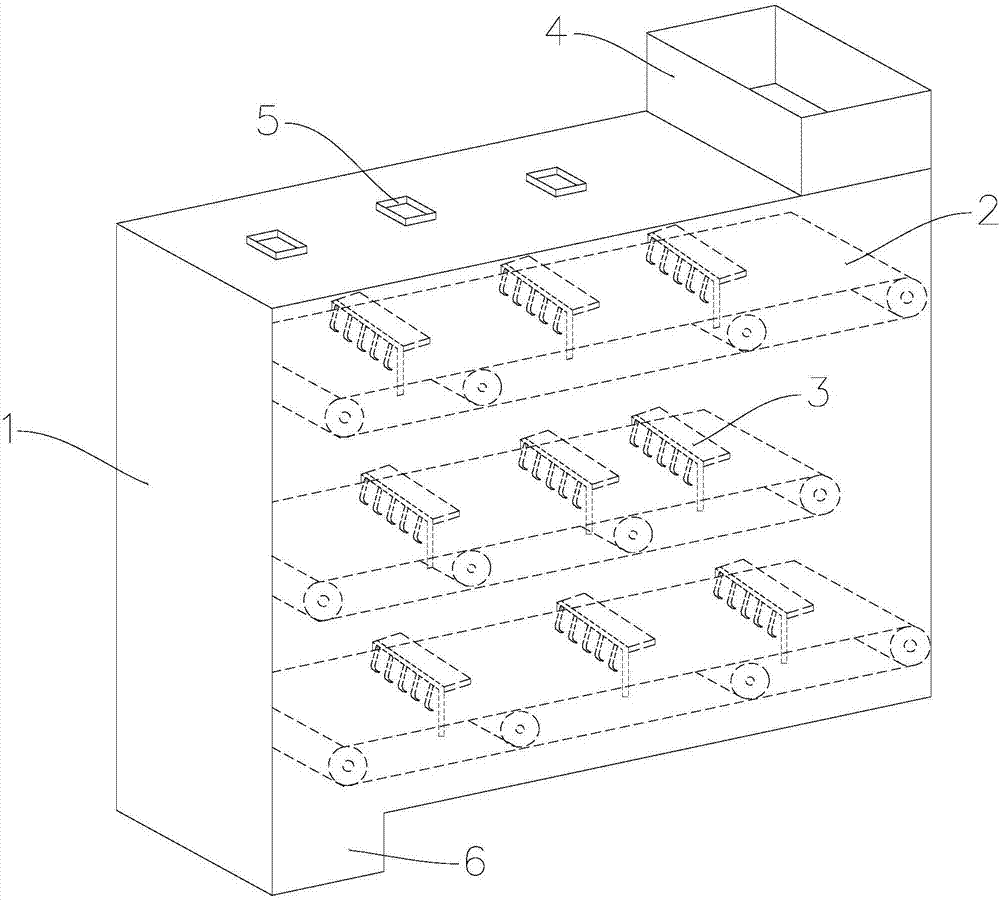
[0017] Such as Figures 1 to 2 As shown, the present invention provides a paint drying device, which includes an oven 1, in which there are multiple layers of conveyor belts 2 that are staggered from top to bottom for conveying paint in the horizontal direction, and the conveyor belts 2 on the lower layer It can accept the paint falling from one end of the conveyor belt 2 on the upper layer, each layer of the conveyor belt 2 is driven by an independently installed motor, and the upper part of each layer of the conveyor belt 2 is evenly spaced along its transmission direction. The drying structure 3 for spreading materials comprises a bracket 30, a drying plate 31 and a material spreading hook 32. The lower end of th...


PUM


Abstract

The invention relates to a paint drying device, which includes an oven, in which there are multiple layers of conveyor belts for conveying the paint along the horizontal direction, and the conveyor belts on the lower layer can receive the paint falling from one end of the upper layer of the conveyor belt. , the upper part of each layer of conveyor belt is evenly spaced along its conveying direction to set a plurality of spreading drying structures. The spreading drying structure includes a bracket, a drying plate and a spreading hook. The upper end of the bracket is connected with the drying plate, and the lower surface of the drying plate is An electric heating device for drying the paint on the conveyor belt below is provided, and a plurality of spreading hooks are provided on the lower surface of the drying plate for spreading the paint on the conveyor belt below to increase the heated area. The beneficial effect of the present invention is that the structure of the multi-layer conveyor belt in the oven can realize continuous feeding and discharging, and can realize continuous drying operation. Increasing the heating area and water vapor distribution area can greatly improve the drying efficiency.

Description

technical field [0001] The invention belongs to the field of powder pigment production, and in particular relates to a pigment drying device. Background technique [0002] Pigment is a substance that can make an object dyed with color. Pigments are soluble and insoluble, and there are inorganic and organic differences. Inorganic pigments are generally mineral substances. Humans have known for a long time to use inorganic pigments, using colored soil and ores, to paint on rock walls and smear their bodies. Organic pigments are generally obtained from plants and marine animals, such as madder indigo, garcinia cambogia, and ancient Roman purple extracted from shellfish. Some pigments are in the form of powder or block. Powdered pigments often need to be dried before packaging, so as to ensure the quality of their preservation. Traditional drying techniques include hot frying, but it is difficult to control the drying process. Temperature, the existing technology also uses a ...

Claims


Application Information

Patent Timeline
IPC IPC(8): F26B17/04F26B23/06F26B25/00F26B25/02
CPCF26B17/04F26B23/06F26B25/002F26B25/02
Inventor 刘耀英
Owner 湖北昇昊色彩科技有限公司
Learn More