
Resource indication method and device based on multiple time buckets

A time period, multi-time technology, applied in the field of communication, can solve the problem of low efficiency of small package business, achieve the effect of efficient resource indication and confirmation, and improve efficiency

Active Publication Date: 2017-07-04
HUAWEI TECH CO LTD
View PDF3 Cites 5 Cited by
  • Summary
  • Abstract
  • Description
  • Claims
  • Application Information

AI Technical Summary

Problems solved by technology

[0005] In view of this, the present invention provides a multi-time period-based resource indication method and device in a wireless local area network, which aggregates multiple uplink data bearing small packet services into one PPDU for transmission, and is used to solve the problem of the efficiency of the existing WLAN equipment in transmitting small packet services. lower question

Method used


Image

  • Resource indication method and device based on multiple time buckets
  • Resource indication method and device based on multiple time buckets
  • Resource indication method and device based on multiple time buckets

Examples


Embodiment 1

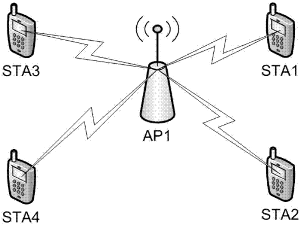
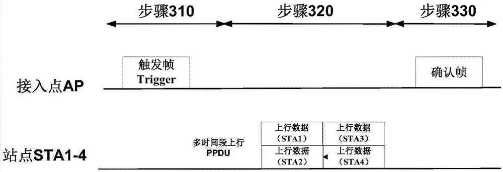
[0070] Embodiment 1 of the present invention provides a multi-time period resource indication method, which can be applied to access points and stations, for example: figure 2 The AP and STA1-STA4 in the AP, the access point and the station can support the next generation WLAN standard, for example: 802.11ax standard. image 3 is a flowchart of the resource indication method, and the specific steps are as follows:

[0071] Step 310: the access point sends a trigger frame.

[0072] Step 320: the access point receives the multi-period uplink physical layer protocol data unit PPDU.

[0073] Step 330: the access point sends an acknowledgment frame.

[0074] Specifically, the detailed structure of the trigger frame mentioned in step 310 is as follows Figure 4 As shown, the trigger frame carries a plurality of time period information fields, and each time period information field of the plurality of time period information fields includes public information and user-specific in...

Embodiment 2

[0111] Please refer to Figure 15 , is a schematic block diagram of a multi-period-based resource indication device in a wireless local area network provided by an embodiment of the present invention. The resource indication device is, for example, an access point, or a dedicated circuit or chip that implements related functions. The resource indicating device 1000 includes a processor 1010 , a memory 1020 , a baseband circuit 1030 , a radio frequency circuit 1040 and an antenna 1050 . The resource indicating means can be figure 2 AP shown in . The AP communicates with STA-STA4.

[0112] Specifically, the processor 1010 controls the operation of the resource indicating device 1000 . The memory 1020 may include read-only memory and random access memory, and provide instructions and data to the processor 1010, and the processor may be a general-purpose processor, a digital signal processor, an application-specific integrated circuit, a field-programmable gate array, or other...


PUM


Abstract

Embodiments of the invention provide a resource indication method based on multiple time buckets. The method comprises the following steps that an access point sends a trigger frame, the trigger frame carries a plurality of time bucket information fields, and each of the time bucket information fields includes public information and user specific information of one or more sites; the access point receives a multi-time-bucket uplink physical protocol data unit (PPDU), wherein the multi-time-bucket uplink physical protocol data unit (PPDU) comprises uplink data sent at the time buckets by the sites; and the access point sends an acknowledgement frame. The embodiments of the invention also provide a corresponding resource indication. Through application of the method and the device in the embodiments of the invention, effective resource indication and confirmation of an 802.11ax system for the time buckets can be realized, and the efficiency for the existing WLAN device to transmit packet business is improved.

Description

technical field [0001] The invention belongs to the technical field of communication, and in particular relates to a multi-time segment-based resource indication method and device. Background technique [0002] The existing wireless local area network (English: Wireless local AccessNetwork, referred to as: WLAN) standard based on OFDM (English: Orthogonal Frequency-Division Multiplexing, Chinese: Orthogonal Frequency Division Multiplexing) technology has gradually evolved from 802.11a, 802.11n, 802.11ac At present, the IEEE (English: Institute of Electrical and Electronic Engineers, Chinese: Institute of Electrical and Electronics Engineers) 802.11 standard organization has launched a new generation of WLAN standard 802.11ax called HEW (High Efficiency WLAN, high-efficiency wireless local area network). The standardization work of 802.11ax can further improve the transmission performance of WLAN in dense user scenarios by introducing OFDMA (Orthogonal Frequency Division Mult...

Claims


Application Information

Patent Timeline
Patent Type & Authority Applications(China)
IPC IPC(8): H04L5/00H04W72/04
CPCH04L5/0007H04W72/21H04L5/0092H04W72/1268H04L5/0044H04L5/0055
Inventor 罗俊张佳胤林英沛
Owner HUAWEI TECH CO LTD
Learn More