
A thermal shock system and a thermal shock machine provided with the system

A technology of cold and heat shock and impact machine, which is applied in the direction of measuring devices, instruments, scientific instruments, etc., can solve the problems of high temperature and low temperature for a long time, high power consumption of mechanical refrigeration, large energy consumption, etc., and achieve rapid and stable temperature rise and fall , High precision temperature control, low energy consumption

Active Publication Date: 2017-07-04
HAITUO INSTR (JIANGSU) CO LTD
View PDF8 Cites 8 Cited by
  • Summary
  • Abstract
  • Description
  • Claims
  • Application Information

AI Technical Summary

Problems solved by technology

Moreover, the refrigeration speed of the above-mentioned cold and heat impact machine is 25°C / min, and the high temperature and low temperature formed last for a long time, and the energy consumption of mechanical refrigeration is relatively large, and the power of the equipment is above 60KW, which has large energy consumption and high cost.

Method used


Image

  • A thermal shock system and a thermal shock machine provided with the system
  • A thermal shock system and a thermal shock machine provided with the system
  • A thermal shock system and a thermal shock machine provided with the system

Examples


Embodiment 1

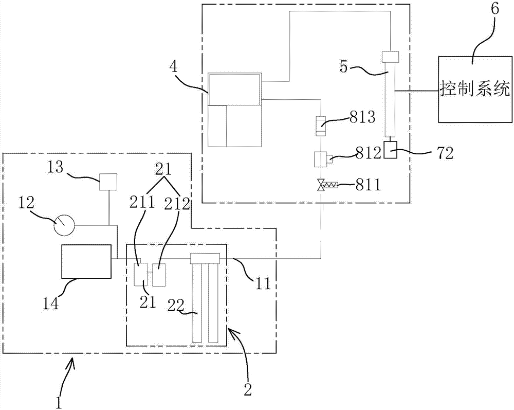
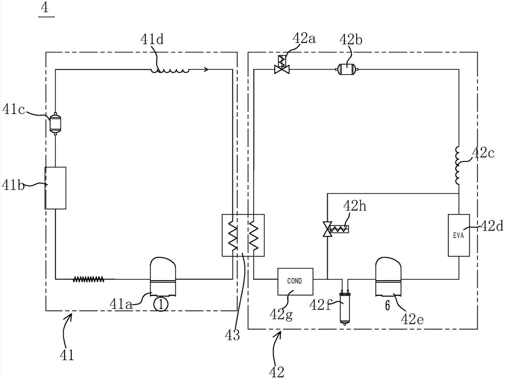
[0044] Please refer to the attached figure 1 , a cold and heat impact system, comprising an air intake system 1, the compressed air pipeline 11 of the intake system 1 is fed with compressed air 14 with a pressure of 70psi-130psi high pressure, preferably air with a pressure of 90psi-110psi, and compressed air The pipeline 11 is connected with an air treatment system 2. The air treatment system 2 includes an oil dust filter 21 and a dry air generator 22 connected in sequence. The oil dust filter 21 includes a dust filter 211 and an oil filter 212, respectively. The oil and dust in the air are filtered to ensure the removal of impurities in the air, and a dry air generator 22 is further installed. The dry air generator 22 is used to remove water droplets in the air, so that the compressed air 14 is fully dried.

[0045] Based on the above settings, an air pressure gauge 12 and an air pressure switch 13 are connected to the air inlet of the compressed air pipeline 11. The air pre...

Embodiment 2

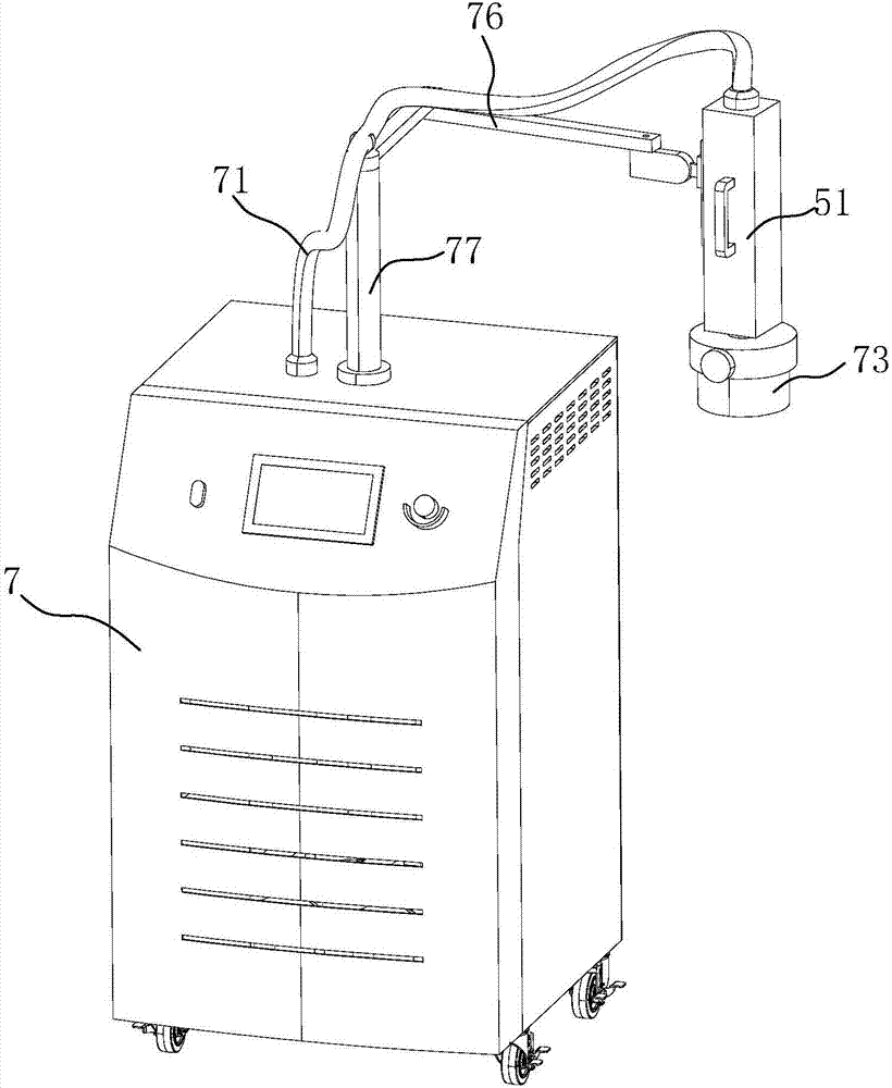
[0053] Please refer to the attached image 3 combined with the attached Figure 6 , a cold and hot impact machine, comprising an impact machine housing 7, an impact machine system is installed inside the impact machine housing 7, the impact machine system includes an air intake system 1, the compressed air pipeline 11 of the air intake system 1 and the compressed air Air 14 pipelines are connected, and are used to pass into 70psi~130psi high-pressure compressed air 14, preferably 90psi~110psi pressure air, compressed air pipeline 11 is arranged on the rear side of impact machine housing 7, in impact machine housing 7 The air pressure gauge 12 and the air pressure switch 13 are connected in sequence with the air inlet of the compressed air pipeline 11, the air pressure gauge 12 is used to detect the air pressure of the compressed air 14, and the air pressure switch 13 is used for high pressure The opening and closing of the compressed air 14 can intuitively see the pressure of...


PUM


Abstract

A thermal shock system and a thermal shock machine provided with the system are provided and overcome the problem that temperature rising and lowering are slow and energy consumption is high in present thermal shock systems. According to a technical scheme, the thermal shock system includes a gas feeding system a compressed air pipeline of which is fed with compressed air having pressure of 70-130 psi; a cooling system connected to the gas feeding system and outputting cooling gas the temperature of which is -80 DEG C or above; a heating system into which the cooling gas is fed and which outputs impact gas having a temperature of -80 DEG C to 225 DEG C; an air processing system communicated with the compressed air pipeline of the gas feeding system so as to purify the compressed air; and a control system used for controlling start and stop of the cooling system and / or the heating system to allow the temperature of gas ejected to be a temperature preset value input by a user, thus achieving rapid temperature lowering and temperature rising, avoiding pre-heating and pre-cooling and avoiding liquid nitrogen assistance. The thermal shock system also has an advantage of greatly reduced energy consumption, thus reducing the cost.

Description

technical field [0001] The present invention relates to a kind of testing mechanical equipment, especially to a kind of test material structure or composite material, which can withstand the continuous environment of extremely high temperature and low temperature in an instant, so as to test its thermal expansion and cooling in the shortest time. Thermal shock tester for chemical or physical changes caused by shrinkage. Background technique [0002] Impact testing machine is the necessary testing equipment for metal, plastic, rubber, electronics, semiconductor, IC, communication and other material industries. To a certain extent, it is possible to detect the chemical change or physical damage of the sample caused by thermal expansion and contraction in the shortest time. [0003] The main technical parameters of the cold and heat shock test equipment in the prior art are: ① Temperature range: -65°C to 100°C (actual effect: -40°C to 100°C); ②Temperature recovery time: 5min; ...

Claims


Application Information

Patent Timeline
Patent Type & Authority Applications(China)
IPC IPC(8): G01N3/60
CPCG01N3/60G01N2203/0222
Inventor 刘冬喜
Owner HAITUO INSTR (JIANGSU) CO LTD
Learn More