
Printing material laying synchronizing mechanism for 3D printing rapid prototyping machine

A technology of 3D printing and synchronizing mechanism, applied in 3D object support structure, solid material additive processing, additive manufacturing, etc., can solve problems such as low work efficiency, and achieve the effect of improving work efficiency

Inactive Publication Date: 2017-07-04
安徽恒利增材制造科技有限公司
View PDF2 Cites 14 Cited by
  • Summary
  • Abstract
  • Description
  • Claims
  • Application Information

AI Technical Summary

Problems solved by technology

However, in most rapid prototyping equipment, the movement of the print head and the laying action are carried out step by step, and the work efficiency is low.

Method used


Image

  • Printing material laying synchronizing mechanism for 3D printing rapid prototyping machine
  • Printing material laying synchronizing mechanism for 3D printing rapid prototyping machine
  • Printing material laying synchronizing mechanism for 3D printing rapid prototyping machine

Examples


Embodiment Construction

[0033] Below in conjunction with accompanying drawing and embodiment of description, specific embodiment of the present invention is described in further detail:

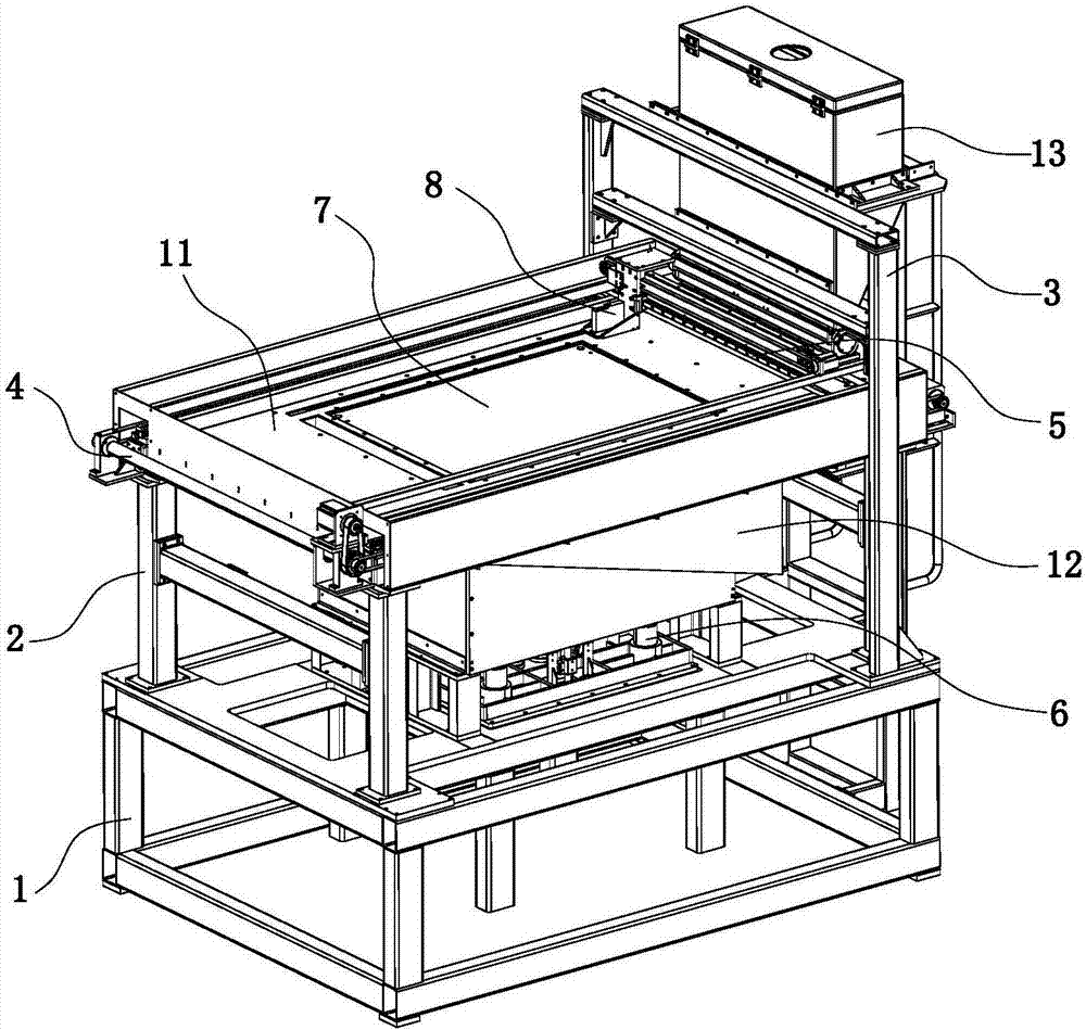
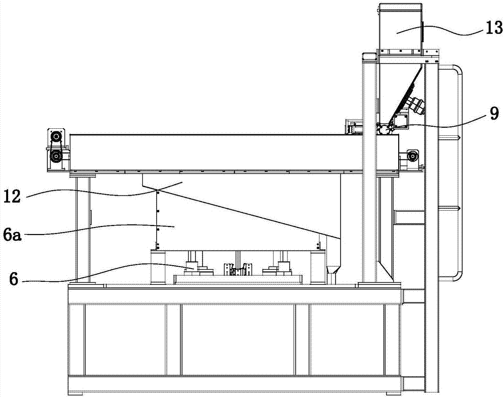
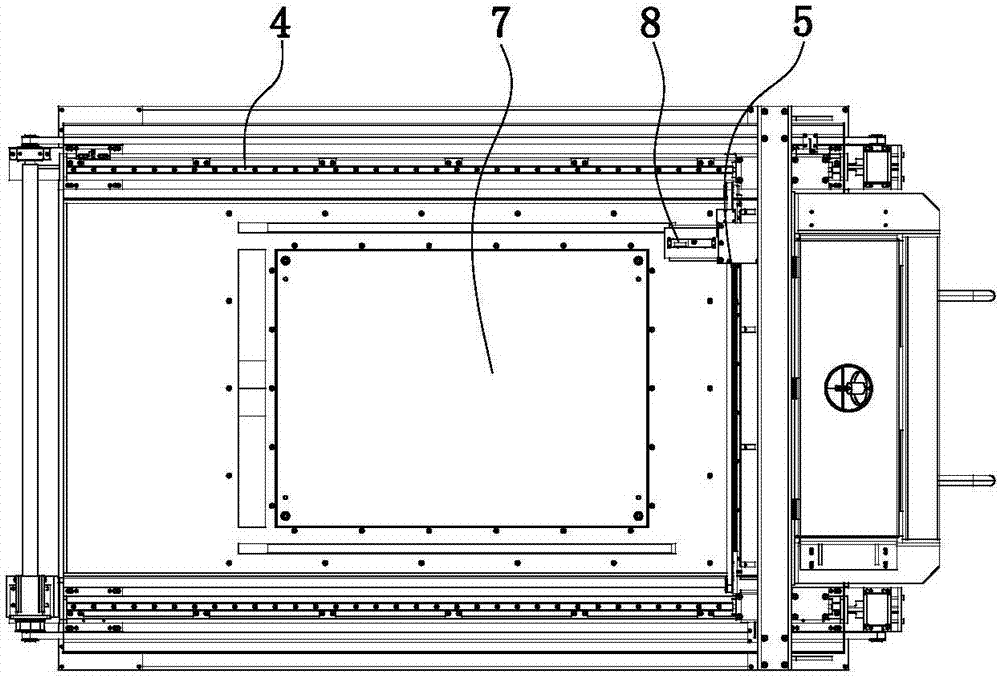
[0034] refer to Figure 1 to Figure 4 A 3D printing rapid prototyping machine based on coated sand material is shown, including a frame, a material cylinder 13, a printing transmission device, a printing material spreading synchronization mechanism and a powder recovery device. The frame includes a lower frame 1, an upper frame Frame 2 and side frame 3, the printing transmission device includes a Y-axis driving guide rail 4, an X-axis driving guide rail 5 and a Z-axis driving device 6, the Y-axis driving guide rail 4 is fixedly installed on the upper frame 2, and the X-axis driving guide rail 4 is fixed on the upper frame 2. The driving guide rail 5 is installed on the Y-axis driving guide rail 4, and the Z-axis driving device 6 is installed between the upper frame 2 and the lower frame 1. The Z-axis driving device ...


PUM


Abstract

The invention relates to the technical field of rapid prototyping technologies, in particular to a printing material laying synchronizing mechanism for a 3D printing rapid prototyping machine. The printing material laying synchronizing mechanism comprises an X-axis drive guide rail and a material laying device which are mounted on a Y-axis drive track. A Y-axis sliding platform is mounted on each of a Y-axis first track and a Y-axis second track through a sliding block. A horizontal mounting plate is arranged across between the two Y-axis sliding platforms. The length direction of the horizontal mounting plate is perpendicular to the Y-axis direction. The X-axis drive guide rail is mounted on the horizontal mounting plate. The two ends of the material laying device are each fixedly connected with one Y-axis sliding platform. A printing head assembly is mounted on the X-axis drive guide rail. The material laying device is parallel to the X-axis drive guide rail and moves synchronous with the X-axis drive guide rail in the Y-axis direction. By the adoption of the printing material laying synchronizing mechanism for the 3D printing rapid prototyping machine, synchronous linkage of the printing head assembly and the material laying device in the Y-axis direction can be achieved, material laying is conducted while printing, and the working efficiency is improved greatly.

Description

technical field [0001] The invention relates to the technical field of rapid prototyping technology, in particular to a printing material laying synchronization mechanism of a 3D printing rapid prototyping machine. Background technique [0002] Rapid Prototyping Technology, also known as Rapid Prototyping Manufacturing (RPM) technology, was born in the late 1980s and is a high-tech manufacturing technology based on the material accumulation method. It is considered to be a major achievement in the manufacturing field in the past 20 years. . It integrates mechanical engineering, CAD, reverse engineering technology, layered manufacturing technology, numerical control technology, material science, and laser technology, and can automatically, directly, quickly and accurately transform design ideas into prototypes with certain functions or directly manufacture parts , so as to provide a high-efficiency and low-cost realization means for parts prototype production and verificatio...

Claims


Application Information

Patent Timeline
Patent Type & Authority Applications(China)
IPC IPC(8): B29C64/153B29C64/321B33Y40/00
CPCB33Y40/00
Inventor 徐宏夏建强宋彬李雨
Owner 安徽恒利增材制造科技有限公司
Learn More