
Machining and locating device, machining machine tool and machining method

A positioning device and positioning mechanism technology, applied in metal processing and other directions, can solve the problems of limiting the working size of the processing table, low machine tool processing productivity, and occupying machine tool processing time, etc., to improve stability and reliability, improve overall processing efficiency, and reduce downtime. The effect of taking time

Active Publication Date: 2017-07-04
SUZHOU GFD AUTOMATION TECH
View PDF9 Cites 1 Cited by
  • Summary
  • Abstract
  • Description
  • Claims
  • Application Information

AI Technical Summary

Problems solved by technology

[0002] The current CNC machine tool processing field mainly requires precise positioning of the workpiece before processing. Generally, the positioning device is integrated with the processing machine tool, which leads to a relatively complicated structure of the entire CNC machine tool and limits the working size of the processing table.
In addition, the chips generated during the processing will inevitably interfere and pollute the positioning fixture of the positioning device, thereby affecting the positioning accuracy
[0003] Moreover, the current processing procedure basically needs to be positioned once before each workpiece is processed. Each positioning takes a certain amount of time, and the processing time of the machine tool is occupied during positioning, which makes the processing head of the machine tool idle.
Especially for plate workpieces with small machining allowance, sometimes the machining time of the machine tool is shorter than the positioning time of the workpiece, which makes the machining productivity of the machine tool very low

Method used


Image

  • Machining and locating device, machining machine tool and machining method
  • Machining and locating device, machining machine tool and machining method
  • Machining and locating device, machining machine tool and machining method

Examples


Embodiment 1

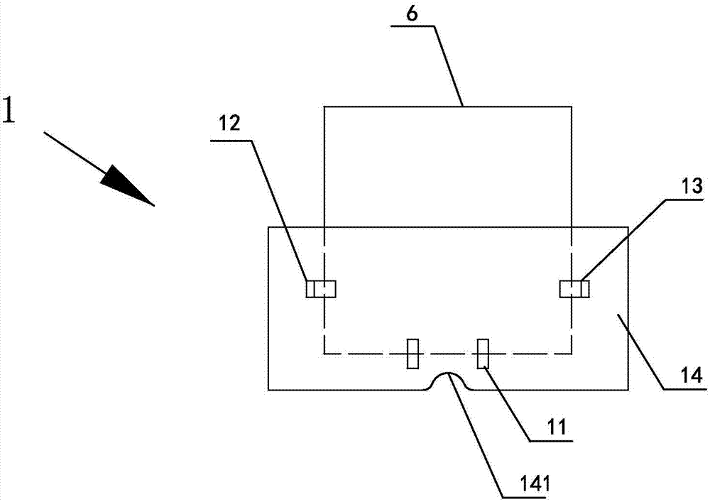
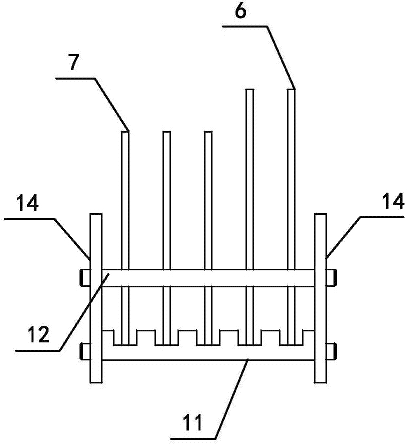
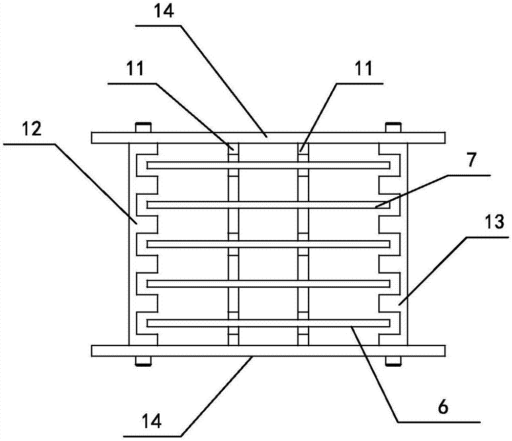
[0044] A preferred embodiment of the present invention provides a processing positioning device, combined with Figure 1-9 As shown, it includes a collection box 1 for loading plates and a positioning platform 2 for carrying the collection box and positioning the plates loaded in the collection box. At least one set of positioning mechanisms is arranged on the positioning platform. The group positioning mechanism corresponds to a collection box, and the positioning mechanism includes: a right positioning rod 22 for positioning the left and right direction of the plate, a floating positioning mechanism 23, and a lower positioning rod 21 for positioning the vertical direction of the plate.

[0045] Described floating positioning mechanism 23 comprises steering guide rod 232, the left positioning rod 231 that is movably connected on the steering guide rod, is used for the guide rod bearing 233 that radially limits the steering guide rod and is connected with the other end of the s...

Embodiment 2

[0053] This embodiment also provides a processing machine tool, combined with Figure 10 and Figure 11 , including the above-mentioned processing and positioning device, and also including a numerical control machine tool 4 and a manipulator 3 for refilling between the processing and positioning device and the numerical control machine tool. Numerical control machine tool can be the numerical control machine tool of any existing known structure, by setting above processing positioning device in front of CNC machine tool workbench or processing table, and the workpiece handling manipulator is set between this processing positioning device and processing table, manipulator can back and forth The processed parts and the parts to be processed are transported and exchanged to form an automatic processing machine tool.

[0054] The workbench on the CNC machine tool can be a mobile workbench or a fixed workbench. A fixture for clamping the workpiece to be processed is installed on ...

Embodiment 3

[0058] The present embodiment provides a kind of processing method, comprises the steps:

[0059] A: After the collection box 1 is placed on the positioning platform 2, the workpiece 6 in the collection box is lifted up to a certain height by the action of the lower positioning rod 21, and then the left positioning rod 231 moves radially to align with the right positioning rod. 22 Accurate positioning of the left and right directions of the workpiece to be processed together;

[0060] B: After the positioning is completed, the manipulator 3 grabs the workpiece to be processed and puts it on the processing table 41 of the CNC machine tool 4. After the processing table completes the clamping of the workpiece to be processed, the processing head 42 of the CNC machine tool processes the workpiece to be processed;

[0061] C: After the processing is completed, the manipulator grabs the processed part 7 and places it in the collection box 1.

[0062] D: The manipulator grabs the ne...


PUM


Abstract

The invention discloses a machining and locating device, a machining machine tool and a machining method. The machining and locating device comprises collecting boxes used for loading to-be-machined pieces and a locating platform which is used for bearing the collecting boxes and locating the to-be-machined pieces loaded in the collecting boxes, wherein at least one locating mechanism is arranged on the locating platform; each locating mechanism corresponds to one collecting box and comprises a right locating rod and a floating location mechanism which are used for locating the to-be-machined pieces in the left-right direction as well as a lower locating rod used for locating the to-be-machined pieces in the vertical direction. The machining and locating functions and the clamping function of the machining platform are separated regionally, locating of multiple to-be-machined pieces can be finished once, independent locating for each to-be-machined piece before machining is not needed, so that time occupied by shutdown of a machine tool machining head waiting for locating of the to-be-machined pieces is reduced, overall machining efficiency of the machine tool is effectively improved, besides, the structure is simplified, stability and reliability of machining are improved, and yield is increased finally.

Description

technical field [0001] The invention relates to the technical field of numerical control machine tool processing, in particular to a processing positioning device, a processing machine tool and a processing method for processing plate workpieces. Background technique [0002] The current CNC machine tool processing field mainly requires precise positioning of the workpiece before processing. Generally, the positioning device is integrated with the processing machine tool, which leads to a relatively complicated structure of the entire CNC machine tool and limits the working size of the processing table. In addition, there are chips generated during the machining process, which will inevitably interfere and pollute the positioning fixture of the positioning device, thereby affecting the positioning accuracy. [0003] Moreover, the current processing procedure basically needs to be positioned once before each workpiece is processed, and each positioning requires a certain amou...

Claims


Application Information

Patent Timeline
Patent Type & Authority Applications(China)
IPC IPC(8): B23Q7/10
CPCB23Q7/10Y02P70/10
Inventor 肖衍盛陈昌永王炎吴勇勇陆平谢舒嵋郭颖俊
Owner SUZHOU GFD AUTOMATION TECH
Learn More