Plate punching device

A punching device and plate technology, applied in the field of mechanical processing, can solve the problems of low efficiency, high processing cost, broken punching head, etc., and achieve the effect of high efficiency and simple structure

Inactive Publication Date: 2017-07-04
CHAOHU UNIV
View PDF8 Cites 0 Cited by
  • Summary
  • Abstract
  • Description
  • Claims
  • Application Information

AI Technical Summary

Problems solved by technology

At present, round holes and waist-shaped holes with a diameter of less than 6mm in thin plate parts are mostly punched by punching dies, while traditional punching dies are formed by integral casting. It is slender and rod-shaped, and the stamping head at the bottom often breaks due to the huge impact force during use. Since the mold is an integral mold, once the stamping head is broken, the entire mold will be scrapped, and the processing cost is high; and the overall The casting mold is heavy, and it takes time and effort to replace and disassemble the mold every time
The existing plate punching device still has the defects of complex structure, low efficiency, and inability to realize automatic unloading

Method used


Image

  • Plate punching device

Examples


Embodiment Construction

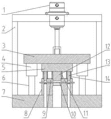
[0011] see figure 1 , a plate punching device, comprising: an upper die 5, a discharge plate 9, a central punch 12, a side punch 13, a die 8, the central punch 12 is fixed at the center of the upper die 5 bottom, Several groups of side punches 13 are fixed on the sides of the bottom of the upper die 5, the outside of the center punch 12 is provided with a center spring 11, the outside of the side punch 13 is provided with a side spring 14, the center spring 11, the upper and lower ends of the side spring 14 Connect with the upper mold 5 and the stripping plate 9 respectively, the bottom of the stripping plate 9 is provided with a die 8, the die 8 is fixed on the base 7, and the center of the stripping plate 9, the die 8, and the base 7 is provided with Aligned central hole, the central hole and the central punch 12 have a common center line, the side of the stripper plate 9, the die 8, the base 7 are provided with aligned side holes, the side hole and the side punch 13 Having...


PUM


Abstract

The invention discloses a plate punching device. The plate punching device comprises an upper die, an unloading plate, a center punch, side punches and a female die. The center punch is fixed to the center position of the bottom of the upper die. The multiple sets of side punches are fixed to the side portion of the bottom of the upper die. Center springs are arranged on the outer side of the center punch, and side springs are arranged on the outer sides of the side punches. The upper ends and the lower ends of the center springs and the side springs are connected with the upper die and the unloading plate. The female die is arranged at the bottom of the unloading plate and is fixed to a base. Center holes aligned with one another are formed in the center positions of the unloading plate, the female die and the base. The center holes and the center punch have the common center line. Side holes which are aligned with one another are formed in the side portions of the unloading plate, the female die and the base. The side holes and the side punches have the common center line. The upper die is fixed to the bottom of an upper die plate, and the upper portion of the upper die plate is connected with a piston rod of a hydraulic oil cylinder. The plate punching device has the beneficial effects of being simple in structure, high in efficiency and capable of achieving automatic unloading and is suitable for punching of various plates.

Description

technical field [0001] The invention belongs to the technical field of mechanical processing, and in particular relates to a plate punching device. Background technique [0002] In the fields of automobiles and construction machinery, thin plate parts are widely used. For example, automobile cover parts include surface and internal parts stamped from thin steel plates with a thickness of less than 3 mm covering the engine, chassis, cab and body of the car. , and its weight accounts for more than 50% of the total amount of steel used in automobiles. At present, round holes and waist-shaped holes with a diameter of less than 6mm in thin plate parts are mostly punched by punching dies, while traditional punching dies are formed by integral casting. It is slender and rod-shaped, and the stamping head at the bottom often breaks due to the huge impact force during use. Since the mold is an integral mold, once the stamping head is broken, the entire mold will be scrapped, and the ...

Claims


Application Information

Patent Timeline
Patent Type & Authority Applications(China)
IPC IPC(8): B21D28/26B21D28/34B21D45/04
CPCB21D28/26B21D28/34B21D45/04
Inventor 孔兵
Owner CHAOHU UNIV
Why Eureka
Try Eureka