Magnetic type positioning punching device

A technology of positioning punching and magnetic suction, which is applied in the field of sheet metal processing, can solve problems such as many burrs on the edge of the hole, affect the quality of the sheet, and be easy to deform, so as to prevent offset and improve reliability.

Inactive Publication Date: 2016-06-22
无锡市通协物资有限公司
View PDF7 Cites 0 Cited by
  • Summary
  • Abstract
  • Description
  • Claims
  • Application Information

AI Technical Summary

Problems solved by technology

The disadvantages of the above-mentioned punching device or punching machine are: only the thin plate can be punched, and there are many burrs on the edge of the hole after punching, and the hole processing quality is not high; after punching, the workpiece, especially the thin plate Metal parts are easily deformed, which affects the quality of the plate

Method used


Image

  • Magnetic type positioning punching device

Examples


Embodiment Construction

[0011] The specific implementation manner of the present invention will be described below in conjunction with the accompanying drawings.

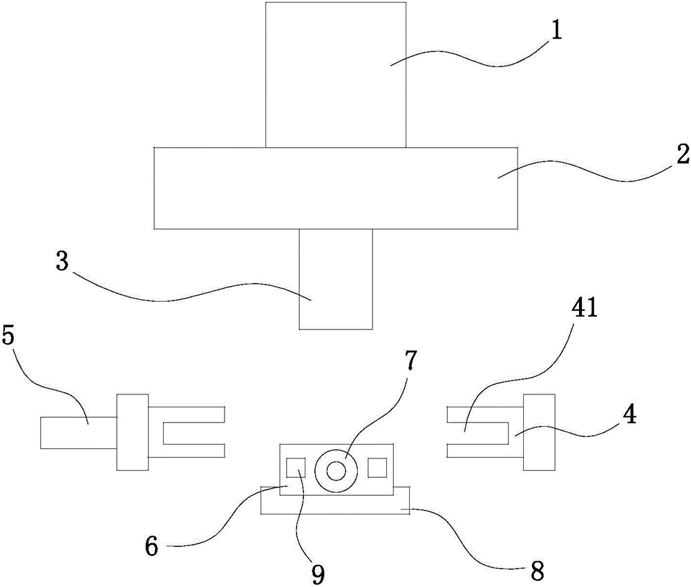
[0012] See figure 1 , the present invention includes a punching driving device 1, an upper template 2 and a punching head 3, and also includes a supporting device and a clamping device located below the punching head 3, and the supporting device includes a base 8 with a chute, the base In the chute of 8, the sliding device cushion block 6, the cushion block 6 is driven by the cylinder 7, and the positioning magnetic block 9 is arranged in the cushion block 6; A clamping groove 41 is provided, wherein a clamping block 4 is connected to the motor 5 ; and a controller for controlling the punching driving device 1 , the cylinder 7 and the motor 5 is also included.

[0013] The above description is an explanation of the present invention, not a limitation of the invention. For the limited scope of the present invention, refer to the claims. Th...


PUM


Abstract

The invention relates to a magnetic type positioning punching device. The magnetic type positioning punching device comprises a punching driving device, an upper die plate and a punching head and further comprises a supporting device and a clamping device, wherein the supporting device and the clamping device are located below the punching head. The supporting device comprises a base provided with a sliding groove. A cushion block is slidably arranged in the sliding groove of the base and driven by an air cylinder. Positioning magnets are arranged in the cushion block. The clamping device comprises clamping blocks which are symmetrically arranged. Clamping grooves are formed in the inner sides of the clamping blocks. One clamping block is connected with a motor. The magnetic type positioning punching device further comprises a controller used for controlling the punching driving device, the air cylinder and the motor. According to the magnetic type positioning punching device, hole machining is achieved in a turning type double-sided punching way, and punching of thick plates is achieved; and the magnets are used for primary positioning, deviation in the turning process is prevented, and thus the punching reliability is improved.

Description

technical field [0001] The invention relates to the technical field of sheet metal processing, in particular to a sheet metal punching machine. Background technique [0002] Existing punching devices or punching machines all include a frame, a bottom mold fixed on the frame, an upper template that moves up and down relative to the frame, and a punch corresponding to the bottom mold is fixed on the upper template. , the upper template is connected with the oil cylinder or cylinder that drives it to move up and down. Driven by the oil cylinder or air cylinder, the upper template drives the punch to move up and down relative to the bottom die, so as to punch out the required holes on the workpiece between the punch and the bottom die. The disadvantages of the above-mentioned punching device or punching machine are: only the thin plate can be punched, and there are many burrs on the edge of the hole after punching, and the hole processing quality is not high; after punching, th...

Claims


Application Information

Patent Timeline
Patent Type & Authority Applications(China)
IPC IPC(8): B21D28/26B21D43/00B21D43/18
Inventor 汪淼
Owner 无锡市通协物资有限公司
Why Eureka
Try Eureka