Automatic surface milling and drilling equipment used for machining

A kind of drilling equipment and machining technology, which is applied in the field of automatic milling and drilling equipment for machining, can solve the problems of increasing production costs, manual operation errors, personnel injuries, etc. high effect

Inactive Publication Date: 2021-01-19
新乡创想自动化科技有限公司
View PDF3 Cites 0 Cited by
  • Summary
  • Abstract
  • Description
  • Claims
  • Application Information

AI Technical Summary

Problems solved by technology

However, at present, most of the lock cylinders are manually processed by various mechanisms, which is inefficient, and the lock cylinder processing requires high precision, and manual operations will inevitably make mistakes, resulting in personnel injury or lock cylinder damage, increasing production costs.

Method used


Image

  • Automatic surface milling and drilling equipment used for machining
  • Automatic surface milling and drilling equipment used for machining
  • Automatic surface milling and drilling equipment used for machining

Examples


Embodiment Construction

[0025] In order to facilitate the understanding of the present invention, the present invention will be described in more detail below in conjunction with the accompanying drawings and specific embodiments. Preferred embodiments of the invention are shown in the accompanying drawings. However, the present invention can be implemented in many different forms and is not limited to the embodiments described in this specification. On the contrary, these embodiments are provided to make the understanding of the disclosure of the present invention more thorough and comprehensive.

[0026] It should be noted that when an element is referred to as being “fixed” to another element, it can be directly on the other element or there can also be an intervening element. When an element is referred to as being "connected to" another element, it can be directly connected to the other element or intervening elements may also be present. The terms "fixed", "integrated", "left", "right" and si...


PUM


Abstract

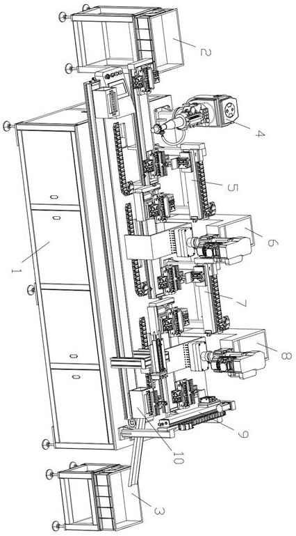
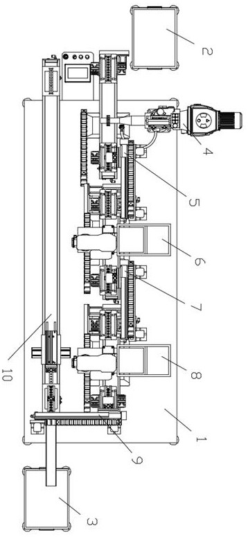
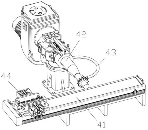
The invention discloses automatic surface milling and drilling equipment used for machining. The automatic surface milling and drilling equipment comprises a worktable, a feeding box and a collectingbox; the feeding box and the collecting box are located at the left side and the right side of the worktable correspondingly; the automatic surface milling and drilling equipment further comprises a lock cylinder surface milling mechanism, a manipulator part taking mechanism I, a lock cylinder punching mechanism, a manipulator part taking mechanism II, a lock cylinder tapping mechanism, a manipulator part taking mechanism III and a product jig reflux mechanism; the lock cylinder surface milling mechanism, the lock cylinder punching mechanism and the lock cylinder tapping mechanism are fixed tothe middle part of the upper surface of the worktable in sequence from left to right; the manipulator part taking mechanism I and the manipulator part taking mechanism II are both fixed to the rear side of the upper surface of the worktable; and the manipulator part taking mechanism I delivers a to-be-machined product to the position of the lock cylinder punching mechanism from the position of the lock cylinder surface milling mechanism. The automatic surface milling and drilling equipment is high in automation degree, effectively improves the machining precision of a lock cylinder, greatly increases the working efficiency and reduces the labor cost, and has good market application value.

Description

technical field [0001] The invention relates to the technical field of powder material packaging equipment, in particular to an automatic face milling and drilling equipment for machining. Background technique [0002] As a must-have product for every household, door locks have a wide range of applications and a large demand for use, accounting for a relatively high proportion in the processing and manufacturing industry. The lock cylinder is the main part that controls the opening of the lock, and is the core part of the lock that is matched with the key. Usually, the lock core adopted on the anti-theft door is a mechanical lock core. The existing mechanical lock core is mainly composed of parts such as a lock casing, a dead bolt, and a lock cylinder. Wherein, the lock cylinder is installed in the lock casing, and the lock cylinder There is a keyhole on the end face of the lock cylinder, and a precise marble structure is installed in the lock cylinder. When using, insert t...

Claims


Application Information

Patent Timeline
Patent Type & Authority Applications(China)
IPC IPC(8): B23P23/06
CPCB23P23/06
Inventor 何佩云
Owner 新乡创想自动化科技有限公司
Why Eureka
Try Eureka