
Permanent magnet linear motor position sensorless control method based on novel disturbance observer

A technology of permanent magnet linear motor and disturbance observer, which is applied in motor generator control, AC motor control, electronic commutation motor control, etc., can solve the problems of high cost, poor reliability, and difficulty in large-scale implementation, and achieve broadband The effect of widening and stability, improving the suppression ability, and broadening the application field

Active Publication Date: 2017-06-30
JIANGSU UNIV
View PDF4 Cites 16 Cited by
  • Summary
  • Abstract
  • Description
  • Claims
  • Application Information

AI Technical Summary

Problems solved by technology

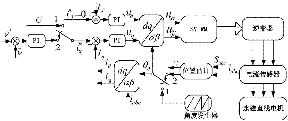
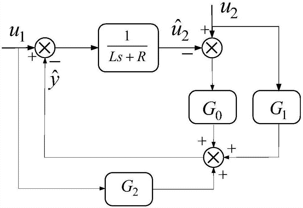
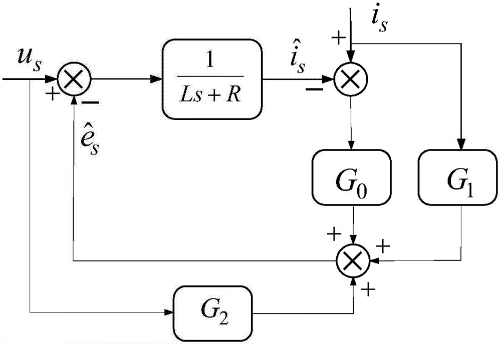
[0004] The purpose of the present invention is to design a new type of disturbance observer to accurately and quickly estimate the position information, and have strong anti-interference ability to high-frequency interference and DC interference, and finally feed back the high-precision position information to the controller to control the motor Reliable operation, the position estimation module based on the disturbance observer replaces the position sensor, thus solving the problems of high cost of use of the position sensor, poor reliability in harsh environments, and difficulty in large-scale implementation

Method used


Image

  • Permanent magnet linear motor position sensorless control method based on novel disturbance observer
  • Permanent magnet linear motor position sensorless control method based on novel disturbance observer
  • Permanent magnet linear motor position sensorless control method based on novel disturbance observer

Examples


Embodiment Construction

[0057] The specific implementation manner of the present invention will be further described below in conjunction with the accompanying drawings.

[0058] Step 1: Detection and calculation of current and voltage

[0059] Detect the three-phase current i of the permanent magnet linear motor a , i b , i c , and after 3s / 2s (Clark) transformation, the current i in the two-phase stationary coordinate system is obtained α and i β . Detect the voltage of the DC power supply and the three-phase duty cycle, and transform it through 3s / 2s (Clark) to obtain the current u in the two-phase static coordinate system α and u β . The calculation method is as follows,

[0060]

[0061]

[0062] Among them, Sa, Sb, Sc are the duty cycle of the controller output, U dc is the DC bus voltage value.

[0063] Step 2, start-up of the permanent magnet linear motor:

[0064] First put the two switches at 1 contact, and the motor is running at the start-up stage. A constant frequency f...


PUM


Abstract

The invention discloses a permanent magnet linear motor position sensorless control method based on a novel disturbance observer. With a voltage equation under the stationary coordinate system of a permanent magnet linear motor adopted as a reconstruction objective, the novel disturbance observer is designed, the input of the disturbance observer is voltages ualpha and ubeta and current ialpha and ibeta under the stationary coordinate system; the output of the disturbance observer is counter electromotive force estimated values under the stationary coordinate system which are represented by symbols described in the descriptions of the invention; the counter electromotive force estimated values are fed into a phase-locked loop structure, and then, position and velocity information can be obtained. The novel disturbance observer high anti-interference ability; and when high-frequency and low-frequency interference exists, position and velocity information can be estimated accurately. According to the position sensorless control method based on the novel disturbance observer, signal injection is not required, and the use of a filter can be avoided, and therefore, high precision and response speed can be realized, and the stable position sensorless operation of the permanent magnet linear motor can be ensured.

Description

technical field [0001] The invention relates to a positionless control method of a linear permanent magnet motor. It is suitable for rail transit, aerospace, CNC machine tools, logistics transportation and other situations where linear motor position sensors cost a lot of cost, cannot be installed, or have poor reliability. Background technique [0002] Permanent magnet linear motors have received more and more applications and attention due to their advantages of simple structure, high efficiency, and large thrust, especially in rail transit. The basic principle of linear motors is the same as that of rotary motors, but the structure is different from Rotating motors are different. The transformation of the structure has expanded new application fields, and at the same time, linear motors and rotary motors meet different needs of society with their own unique advantages. However, the use of permanent magnet linear motors often requires a position sensor. On the one hand, ...

Claims


Application Information

Patent Timeline
IPC IPC(8): H02P21/24H02P21/18H02P21/13H02P21/34H02P25/06
CPCH02P21/13H02P25/06
Inventor 赵文祥矫帅邱先群吴彬玉陈前许德志胡德水
Owner JIANGSU UNIV
Learn More