Optical component debugging method and tool based on infrared imaging

A technology of optical components and debugging methods, applied in the field of installation and adjustment of various infrared optical systems, can solve the problems of tight design tolerances, inability to guarantee processing, and difficult processing of components, simplifying installation difficulties, and eliminating clamping stress. The influence of the surface shape of the test piece and the effect of reducing the difficulty of processing

Active Publication Date: 2019-05-03
SHANGHAI AEROSPACE CONTROL TECH INST
View PDF14 Cites 0 Cited by
  • Summary
  • Abstract
  • Description
  • Claims
  • Application Information

AI Technical Summary

Problems solved by technology

However, due to the tight design tolerances of individual complex systems or the difficulty in processing components, the processing cannot be guaranteed

Method used


Image

  • Optical component debugging method and tool based on infrared imaging
  • Optical component debugging method and tool based on infrared imaging
  • Optical component debugging method and tool based on infrared imaging

Examples


Embodiment Construction

[0053] Hereinafter, in conjunction with the drawings, a preferred specific example is described in detail to further illustrate the present invention.

[0054] The present invention provides a method and tool for debugging optical components based on infrared imaging, including: testing and adjusting the inclination of a tilted spherical secondary reflector; testing and adjusting the eccentricity of a plano-convex lens; controlling the verticality of the optical axis of the primary reflector; and , Detect and adjust the posture of the aspheric main reflector.

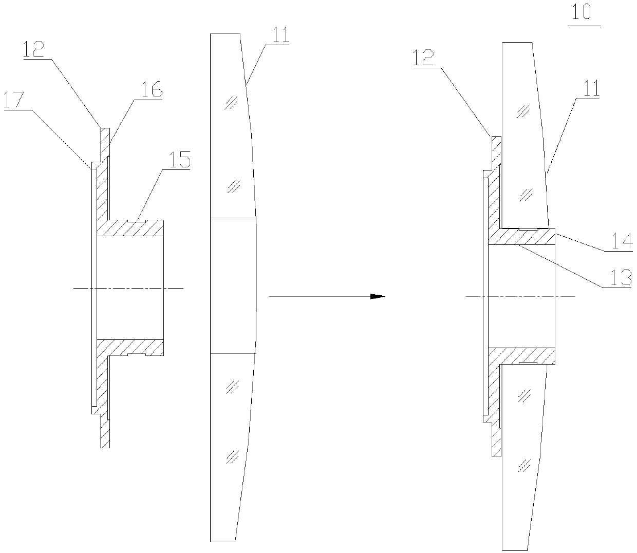
[0055] Such as Figure 1a~Figure 1d As shown, it is a schematic diagram of the step-by-step assembly of the tilted spherical secondary mirror. The secondary mirror 11 is glued on the mirror base 12 to form a component ( Figure 1a ), and then assembled on the column of the system. The through hole in the middle of the secondary mirror 11 is sleeved on the outer wall of the inner hole 13 of the mirror holder 12, and the first...


PUM


Abstract

The invention relates to an optical component debugging method and tool based on infrared imaging. By testing and adjusting a slant spherical surface minor reflector inclination, the machining and correcting difficulty of a minor reflector element on the inclination is lowered. By testing and adjusting an eccentricity of a plano-convex lens, the eccentricity of the plano-convex lens is corrected and controlled, and the problem is solved that the eccentricity is uncontrollable caused by factors of nonuniform adhesive layer thicknesses and the like. When main reflector optical axis perpendicularity is controlled, through modes of arranging a glue overflowing slot of technical equipment, reasonably giving positioning matching tolerance and the like, the main reflector adhering position is accurate, and the inclination is guaranteed. When an aspheric main reflector surface type is detected, by reasonably designing compensating mirror installation and fixing the technical equipment, the installation difficulty of the aspheric main reflector mirror is simplified, and the installation stability is improved; by reliably fixing a main reflector, the influence of a common three-jaw clamping groove clamp stress on a detected piece surface type is eliminated; in the main reflector measuring process, through a posture adjustment technique, the measuring efficiency is improved.

Description

Technical field [0001] The invention belongs to an optical component debugging method based on infrared imaging, relates to the debugging and detection of various types of infrared optical components and tooling design, and is suitable for the assembly and adjustment of various infrared optical systems. Background technique [0002] The installation of the optical components of the infrared imaging optical system usually depends on design tolerances and processing guarantees. However, due to the tight design tolerances of individual more complex systems or the difficulty of component processing, processing cannot be guaranteed. It requires scientific and ingenious assembly and adjustment technology to ensure the assembly accuracy of the components, so as to ensure that the imaging of the optical system meets the design requirements. Summary of the invention [0003] The purpose of the present invention is to provide a method and tool for debugging optical components based on infr...

Claims


Application Information

Patent Timeline
Patent Type & Authority Patents(China)
IPC IPC(8): G02B27/62
CPCG02B27/62
Inventor 朱绍纯坎金艳李晓哲徐松马天义
Owner SHANGHAI AEROSPACE CONTROL TECH INST
Why Eureka
Try Eureka