
While-drilling advanced forecasting apparent resistivity measuring system and method

A technology of apparent resistivity and advanced prediction, applied in electromagnetic wave detection, earthwork drilling, material impedance and other directions, can solve the problems of large influence of observation results, no effective signal measurement, single detection parameter, etc., to increase effective detection. Depth, improve detection efficiency, and improve the effect of detection accuracy

Inactive Publication Date: 2017-06-30
武汉地大华睿地学技术有限公司
View PDF7 Cites 6 Cited by
  • Summary
  • Abstract
  • Description
  • Claims
  • Application Information

AI Technical Summary

Problems solved by technology

Except for the drilling advance water detection method above, other geophysical methods are all advanced detection methods for tunnels, roadways or working faces. Various metal facilities such as I-beam support, bolt support, and conveyor belt support have a great influence on the observation results. At the same time, the site construction design, data observation, and result analysis are complex, and the detection parameters are single, resulting in multiple solutions.
Moreover, the advanced drilling water exploration method is to put the detection probe into the borehole for detection after the borehole is formed, which is similar to the logging technology on the ground. It is impossible to carry out the drilling advanced water exploration work after the borehole collapses. , the construction is basically carried out by means of push rod measurement; the push rod is limited by its own weight and the friction of the hole wall, generally the depth is less than 40 meters, and this method cannot overcome the problem of excessive grounding resistance, resulting in the supply current Weak or even no effective signal can be measured, and the detection effect is useless

Method used


Image

  • While-drilling advanced forecasting apparent resistivity measuring system and method
  • While-drilling advanced forecasting apparent resistivity measuring system and method
  • While-drilling advanced forecasting apparent resistivity measuring system and method

Examples


Embodiment Construction

[0040] The principles and features of the present invention are described below in conjunction with the accompanying drawings, and the examples given are only used to explain the present invention, and are not intended to limit the scope of the present invention.

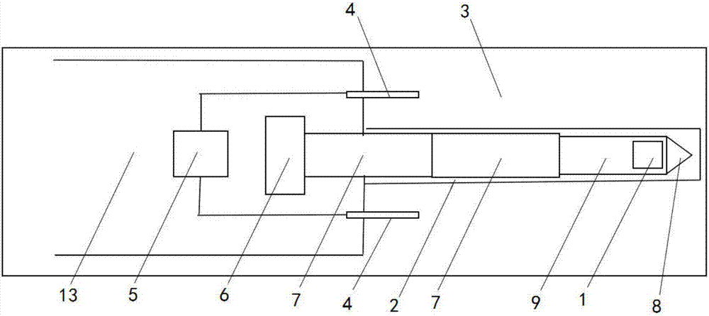
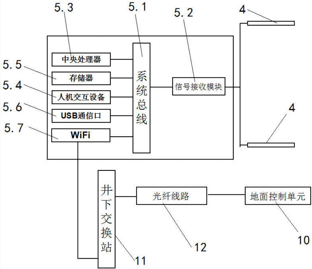
[0041] like figure 1 As shown, an apparent resistivity measurement system for advanced forecasting while drilling includes a magnetic dipole antenna 1 installed in the drilling device and a plurality of receiving electrodes 4 distributed in the surrounding rock 3 around the borehole 2, and with A plurality of receiving electrodes 4 connected field host 5, the drilling device drills the borehole 2 in the surrounding rock 3 in the roadway 13, the field host 5 is placed in the roadway 13, the magnetic dipole antenna 1, its It is used to automatically output pulsed electromagnetic waves in real time during the process of drilling in the borehole 2 with the drilling device, and to form an induced electromagnetic field in...


PUM


Abstract

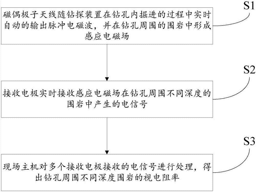
The invention relates to a while-drilling advanced forecasting apparent resistivity measuring system and method. The while-drilling advanced forecasting apparent resistivity measuring system comprises a magnetic-dipole antenna installed in a drilling rig, a plurality of receiving electrodes distributed in surrounding rocks around a drill hole and an on-site main machine connected with the multiple receiving electrodes. The magnetic-dipole antenna is used for automatically outputting pulse electromagnetic waves in real time in the process of advancing in the drill hole along with the drilling rig and forming induced electromagnetic fields in the different-depth surrounding rocks around the drill hole; the receiving electrodes are used for real-time receiving of electric signals generated in the different-depth surrounding rocks around the drill hole by the induced electromagnetic fields; and the main machine is used for processing the electric signals received by the multiple receiving electrodes and obtaining the apparent resistivity of the different-depth surrounding rocks around the drill hole. According to the while-drilling advanced forecasting apparent resistivity measuring system and method, detection precision of geophysical exploration can be improved, the control range of advanced hole exploration can be increased as well, detection efficiency of advanced hole exploration can be improved, and the quantity of the arranged drill holes is reduced.

Description

technical field [0001] The invention relates to the technical field of geophysical electrical prospecting and drilling, in particular to an apparent resistivity measurement system and method for advanced prediction while drilling. Background technique [0002] Advanced detection is mainly to detect the direction of tunnel and roadway excavation by direct or indirect methods at the head of the tunnel, to detect whether there are harmful geological structures or rich water bodies and water guide channels ahead, and to provide detailed detection data for safe tunneling. At present, the direct method used for advanced detection of coal mines is the drilling method, and the indirect method is the geophysical method; although the drilling method is relatively reliable for the drilling results of a single borehole, the drilling results are only valid for a single borehole, and it is impossible to detect from point to area As a result, the drilling methods in key detection areas can...

Claims


Application Information

Patent Timeline
Patent Type & Authority Applications(China)
IPC IPC(8): E21B49/00G01V3/12G01N27/02
CPCE21B49/00G01N27/02G01V3/12
Inventor 梁庆九
Owner 武汉地大华睿地学技术有限公司
Learn More