
Terahertz detector with integration of dipole antennas and NMOS temperature sensor

A technology of terahertz detectors and dipole antennas, applied in the field of terahertz detectors, can solve problems such as increased cost, complexity, and large chip area, and achieve the effects of enhanced temperature detection capabilities, reduced costs, and area savings

Inactive Publication Date: 2017-06-23
TIANJIN UNIV
View PDF9 Cites 3 Cited by
  • Summary
  • Abstract
  • Description
  • Claims
  • Application Information

AI Technical Summary

Problems solved by technology

At present, most of the temperature sensing parts used in terahertz thermal detection use PTAT (proportional to absolute temperature) circuits or temperature sensing devices such as triodes, but PTAT circuits are very complicated and require a large number of devices, occupying a relatively large The large chip area has caused an increase in cost; devices such as triodes and diodes occupy a larger area than NMOS tubes under the CMOS (Complementary Metal Oxide Semiconductor) process
On the other hand, the sensor adopts MEMS (Micro-Electro-Mechanical System) technology, which greatly increases the process difficulty and cost compared with the CMOS process.

Method used


Image

  • Terahertz detector with integration of dipole antennas and NMOS temperature sensor
  • Terahertz detector with integration of dipole antennas and NMOS temperature sensor
  • Terahertz detector with integration of dipole antennas and NMOS temperature sensor

Examples


Embodiment 1

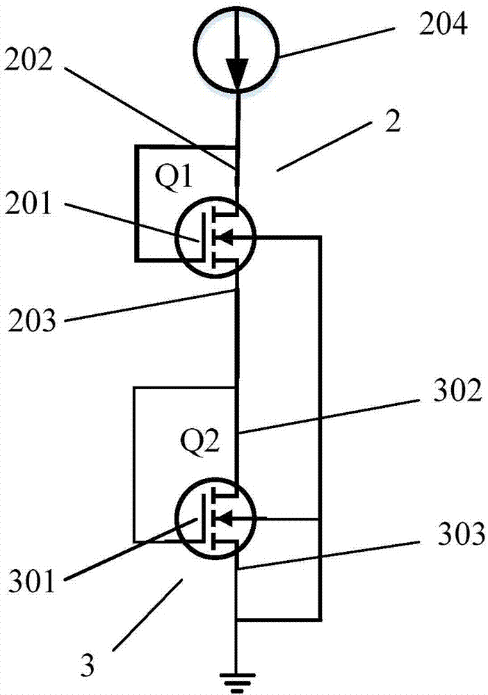
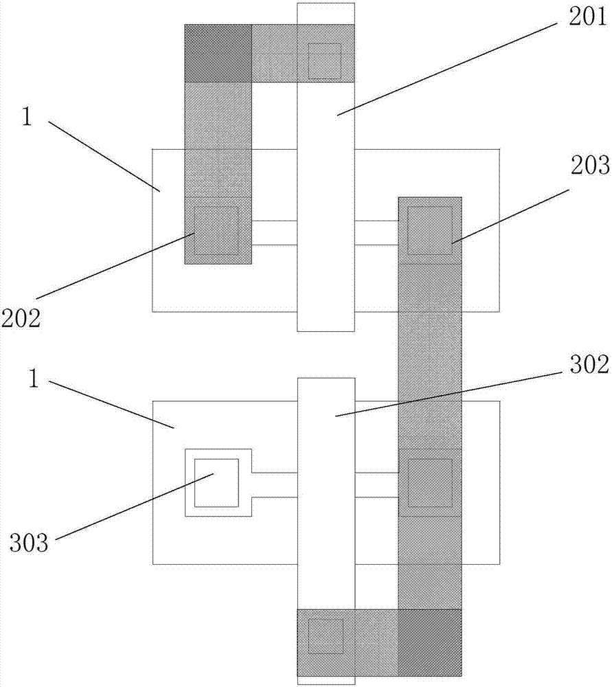
[0035] A terahertz detector integrating a dipole antenna and an NMOS temperature sensor, including a silicon substrate and a first NMOS transistor 2 and a second NMOS transistor 3 arranged on a silicon substrate 1; at a frequency of 2.66THz, According to formula (3) and formula (4), it can be obtained that the arm length of the corresponding dipole antenna (ie, the gate length of the first and second NMOS transistors) is 14.5um. After simulation, the distance between the two antennas (the distance between the grids of the first and second NMOS transistors) is 1um, and the width of each antenna (the grids of the first and second NMOS transistors) is 3um.

[0036] The S11 parameter image of the dipole antenna at 2.66THz is as follows Figure 5 shown. because Indicates the absorption rate of the antenna. The smaller the value of the entire expression, the higher the absorption rate of the antenna. It can be seen that S 11 The parameter reaches the minimum value at about 2.66T...

Embodiment 2

[0038] A terahertz detector integrating a dipole antenna and an NMOS temperature sensor, including a silicon substrate and a first NMOS transistor 2 and a second NMOS transistor 3 arranged on a silicon substrate 1; at a frequency of 29.6THz, According to formula (3) and formula (4), it can be obtained that the arm length of the corresponding dipole antenna (that is, the gate length of the first and second NMOS transistors) is 1.3um. After simulation, the distance between the two antennas (the distance between the grids of the first and second NMOS transistors) is 0.34um, and the width of each antenna (the grids of the first and second NMOS transistors) is 0.34um.

[0039] The S11 parameter image of the dipole antenna at 29.6THz is as Figure 6 shown. It can be seen that the value of the entire image is the smallest when the S11 parameter is at 29.6THz, which indicates that the antenna performance is the best at this time, and it also indicates that the calculated antenna length...

Embodiment 3

[0041] A terahertz detector integrating a dipole antenna and an NMOS temperature sensor, including a silicon substrate and a first NMOS transistor 2 and a second NMOS transistor 3 arranged on a silicon substrate 1; at a frequency of 16.3THz, According to formula (3) and formula (4), it can be obtained that the arm length of the corresponding dipole antenna (that is, the grid spacing of the first and second NMOS transistors) is 1um, and the distance between each antenna (the grid of the first and second NMOS transistors) The width is 0.24um.

[0042] The S11 parameter image of the dipole antenna at 16.3THz is as Figure 7 shown. It can be seen that the value of the entire image is the smallest when the S11 parameter is at 16.3THz, indicating that the antenna performance at this time is the best, and it also indicates that the calculated antenna length at this time can echo well with the terahertz frequency.


PUM


Abstract

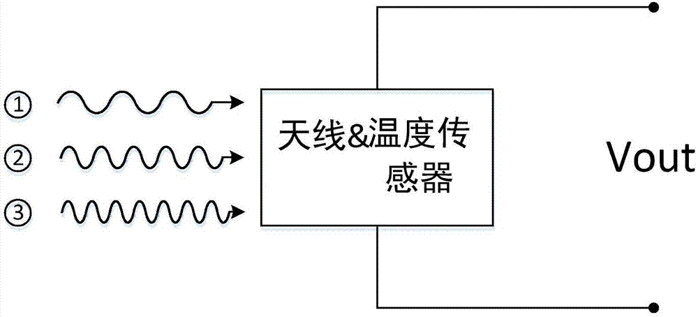
The invention discloses a terahertz detector with the integration of dipole antennas and an NMOS temperature sensor. The detector comprises a silicon substrate and first and second NMOS tubes arranged on the substrate. The gates of the two NMOS tube are respectively connected to the drain electrode. The drain electrode of the first NMOS tube is connected to a power supply, and the source electrode of the first NMOS tube is connected to the drain electrode of the second NMOS tube. The source electrode of the second NMOS tube is grounded. The first NMOS tube and the second NMOS tube are the same, the gate lengths of the two NMOS tubes are 1.28 to 128.25 micron meters, and the NMOS tubes are used as dipole antennas. According to the terahertz detector, under the standard CMOS technology, the gate of the NMOS tubes are used as the dipole antenna structures of the detector, the integration of the antennas and the temperature sensor is realized, the chip area is reduced, and the cost is saved.

Description

technical field [0001] The invention relates to the field of semiconductor electromagnetic wave detection, in particular to a terahertz detector integrating a dipole antenna and an NMOS temperature sensor. Background technique [0002] Terahertz wave refers to an electromagnetic wave between the millimeter wave band and the infrared band. The terahertz frequency band is defined between 0.3THz and 30THz (wavelength is 1mm-10μm), which belongs to the junction area of ​​electronics and optics. Compared with X-rays, terahertz waves have lower energy and better penetration than visible light. These characteristics make terahertz imaging have great development prospects in safety monitoring and medical care. [0003] There are many types of terahertz detectors, such as antenna-coupled FET (Field Effect Transistor) self-mixing detectors, antenna-coupled Schottky diode detectors, heterojunction detectors, and antenna-coupled terahertz thermal detectors. These detectors all have the...

Claims


Application Information

Patent Timeline
Patent Type & Authority Applications(China)
IPC IPC(8): H01Q1/22H01Q1/38H01L27/04
CPCH01Q1/2283H01L27/04H01Q1/38
Inventor 陈霏李子蒙
Owner TIANJIN UNIV
Learn More