An equipment system that utilizes waste heat from a cement plant to realize carbon dioxide cycle power generation
A waste heat and equipment technology, applied in the equipment system field of carbon dioxide cycle power generation, can solve problems such as inappropriate
- Summary
- Abstract
- Description
- Claims
- Application Information
AI Technical Summary
Problems solved by technology
Method used
Image
Examples
Embodiment 1
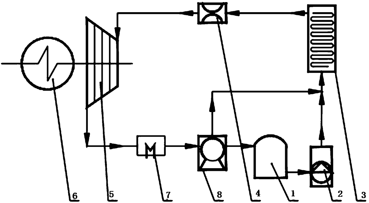
[0053] Such as figure 1 As shown, the present invention provides an equipment system for utilizing the waste heat of a cement plant to realize carbon dioxide cycle power generation, mainly including liquid CO 2 Storage tank 1, high pressure pumping device 2, CO 2 Energy storage device 3, flow stabilizer 4, turbine / piston expander 5, generator 6, cooling device 7, compression device 8, the liquid CO 2 The outlet of the storage tank 1 is connected with the inlet of the high-pressure pumping device 2, and the outlet of the high-pressure pumping device 2 is connected with the CO 2 The inlet of energy storage device 3 is connected, CO 2 The outlet of the energy storage device 3 is connected to the inlet of the flow stabilizer 4, the outlet of the flow stabilizer 4 is connected to the inlet of the turbine / piston expander 5, the turbine / piston expander 5 is connected to the generator 6 shaft, and the turbine / The outlet of the piston expander 5 is connected with the inlet of the ...
Embodiment 2
[0059] Such as Figure 4 As shown, the difference between Embodiment 2 and Embodiment 1 is that it also includes a regenerator 9; the outlet of the turbine / piston expander 5 communicates with the low-pressure fluid inlet of the regenerator 9, and the low-pressure fluid inlet of the regenerator 9 The fluid outlet is connected to the inlet of the cooling device 7, the outlet of the cooling device 7 is connected to the inlet of the compression device 8, and the outlet of the compression device 8 is respectively connected to the high-pressure fluid inlet of the regenerator 9, the CO 2 Inlet of energy storage device 3, liquid CO 2 The inlet of storage tank 1 is connected. After the turbine or piston expander 5 works and releases energy, low-pressure CO is discharged. 2 Fluid, low pressure CO 2 After the fluid recovers the waste heat through the regenerator 9, it is cooled by the cooling device 7, compressed by the compression device 8 and sent to liquid CO 2 The fluid in the st...
Embodiment 3
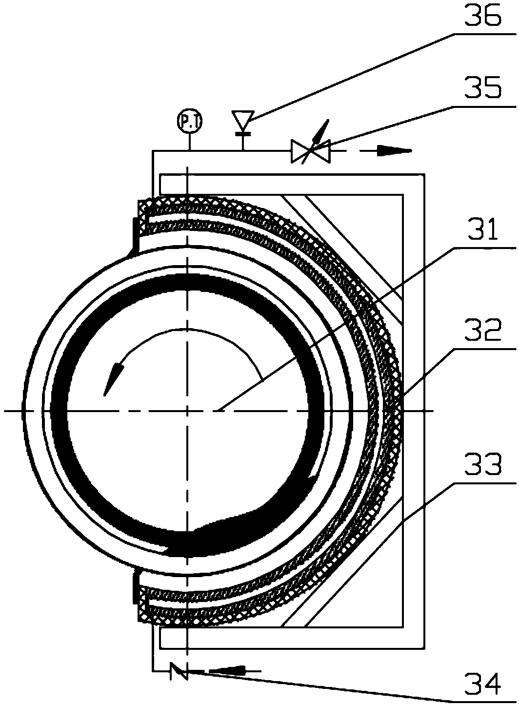
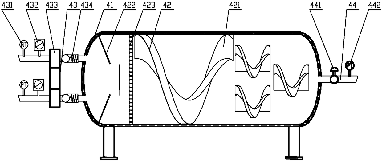
[0061] Such as Figure 5 As shown, the difference between Example 3 and Example 1 is that the CO 2 Energy storage device 3 is built-in CO for the kiln hood 2 The energy storage device 3a and the high temperature section of the kiln shell radiate CO 2 Combination of energy storage device 3b, built-in CO in the kiln hood 2 The energy storage device 3a and the high temperature section of the kiln shell radiate CO 2 The specific structure of energy storage device 3b can refer to Figure 4 , according to the specific device body, the structure of the device body changes, but the components in the device remain unchanged; wherein, the outlet of the high-pressure pumping device 2 is connected to the built-in CO of the kiln head cover respectively. 2 The inlet of the energy storage device 3a and the high temperature section of the kiln shell radiate CO 2 The inlet of the energy storage device 3b is connected, and the kiln head cover is built with CO 2 The outlet of the energy st...
PUM
 Abstract
Description
Claims
Application Information
 - R&D
- Intellectual Property
- Life Sciences
- Materials
- Tech Scout
- Unparalleled Data Quality
- Higher Quality Content
- 60% Fewer Hallucinations
Browse by: Latest US Patents, China's latest patents, Technical Efficacy Thesaurus, Application Domain, Technology Topic, Popular Technical Reports.
© 2025 PatSnap. All rights reserved.Legal|Privacy policy|Modern Slavery Act Transparency Statement|Sitemap|About US| Contact US: help@patsnap.com


