
A bridge pavement cleaning device

A road surface cleaning and bridge technology, applied in road surface cleaning, cleaning methods, construction, etc., can solve the problems of inconvenient storage and storage, difficulty of cleaning work, and limited cleaning times of cleaning vehicles

Active Publication Date: 2018-12-14
张家港和智珅知识产权有限公司
View PDF6 Cites 0 Cited by
  • Summary
  • Abstract
  • Description
  • Claims
  • Application Information

AI Technical Summary

Problems solved by technology

[0002] In the daily maintenance of the bridge, the cleaning of the bridge road surface is an important cleaning measure. In the existing ones, the cleaning vehicle is generally used for cleaning. However, the number of cleaning vehicles per day is limited and there are great limitations. After a sudden traffic accident on the bridge The cleaning is usually done by the maintenance personnel through the external water pipe. However, due to the long water pipe, it is inconvenient when retracting and unwinding, which brings great difficulty to the cleaning work. Therefore, the installation of emergency cleaning devices on the bridge is to ensure the cleanliness of the bridge road surface. and important measures for the normal passage of vehicles

Method used


Image

  • A bridge pavement cleaning device
  • A bridge pavement cleaning device
  • A bridge pavement cleaning device

Examples


Embodiment Construction

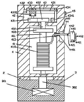
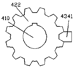
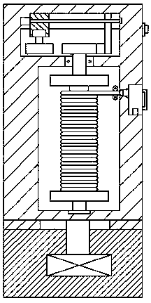
[0021] Such as Figure 1-Figure 6 As shown, a bridge pavement cleaning device of the present invention includes a base 3 and a body 4 arranged above the base 3, the inner bottom of the base 3 is provided with a third driving machine 301, and the top of the third driving machine 301 is Connected with a rotating rod 302, the top of the rotating rod 302 passes through the wall of the base 3 and is fixedly connected with the bottom of the body 4, a bearing 2 is arranged between the body 4 and the base 3, and the body 4 A first accommodation chamber 41 is arranged inside, and a second accommodation chamber 42 is arranged inside the body 4 at the top of the first accommodation chamber 41, and a sliding groove 43 is provided on the inner top wall of the second accommodation chamber 42, and the first accommodation chamber 42 A snap-in groove 44 is provided in the outer wall of the body 4 on the right side of the accommodating chamber 41, and a through groove 440 is provided between th...


PUM


Abstract

The invention discloses a bridge road surface washing device. The device comprises a base and a machine body arranged above the base, the bottom inside the base is provided with a third driving machine, the top of the third driving machine is connected to a rotary rod, the top of the rotary rod penetrates through the wall body of the base and is fixedly connected to the bottom of the machine body, a bearing is arranged between the machine body and the base, the machine body is internally provided with a first accommodation cavity, the machine body at the top of the first accommodation cavity is internally provided with a second accommodation cavity, the inner top wall of the second accommodation cavity is provided with a slide groove, the outer wall of the machine body at the right side of the first accommodation cavity is internally provided with a blocking groove, a through groove is formed between the blocking groove and the first accommodation cavity, the first accommodation cavity is internally provided with a rotary shaft which is arranged to extend up and down, the top of the rotary shaft penetrates through the wall body inside the machine body, extends into the second accommodation cavity and is in rotary and cooperative connection with the second accommodation cavity, a rotor drum is fixedly arranged on the rotary shaft in the first accommodation cavity, and clapboards are symmetrically arranged at the upper and lower two sides of the rotor drum. The bridge road surface washing device is simple in structure and convenient to operate, reduces the labor amount of workers, and improves the cleaning efficiency.

Description

technical field [0001] The invention relates to the technical field of bridge facilities, in particular to a bridge road surface cleaning device. Background technique [0002] In the daily maintenance of the bridge, the cleaning of the bridge road surface is an important cleaning measure. In the existing ones, the cleaning vehicle is generally used for cleaning. However, the number of cleaning vehicles per day is limited and there are great limitations. After a sudden traffic accident on the bridge The cleaning is usually done by the maintenance personnel through the external water pipe. However, due to the long water pipe, it is inconvenient when retracting and unwinding, which brings great difficulty to the cleaning work. Therefore, the installation of emergency cleaning devices on the bridge is to ensure the cleanliness of the bridge road surface. And important measures for the normal passage of vehicles. Contents of the invention [0003] The technical problem to be s...

Claims


Application Information

Patent Timeline
Patent Type & Authority Patents(China)
IPC IPC(8): E01H3/04
CPCE01H3/04
Inventor 马浩晓
Owner 张家港和智珅知识产权有限公司
Learn More