
An impeller welding jig with mold groove positioning and auxiliary blanking function and its control method

A welding fixture and auxiliary blanking technology, applied in auxiliary welding equipment, auxiliary devices, welding equipment, etc., can solve the problems of increasing production costs, reducing production efficiency, and unsightly welds, achieving zero scrap rate and high production efficiency , Welding quality and reliable effect

Inactive Publication Date: 2018-06-15
WUHAN CHUTIAN IND LASER EQUIP
View PDF6 Cites 0 Cited by
  • Summary
  • Abstract
  • Description
  • Claims
  • Application Information

AI Technical Summary

Problems solved by technology

[0002] In the prior art, there are manual welding, laser welding, etc. for impeller welding, but the welding efficiency is low, the labor intensity is low, the welding quality is low, the weld seam is not beautiful, and the scrap rate is high, which increases the production cost and reduces the production efficiency.

Method used


Image

  • An impeller welding jig with mold groove positioning and auxiliary blanking function and its control method
  • An impeller welding jig with mold groove positioning and auxiliary blanking function and its control method
  • An impeller welding jig with mold groove positioning and auxiliary blanking function and its control method

Examples


Embodiment Construction

[0017] The following examples are used to illustrate the present invention, but are not intended to limit the scope of the present invention.

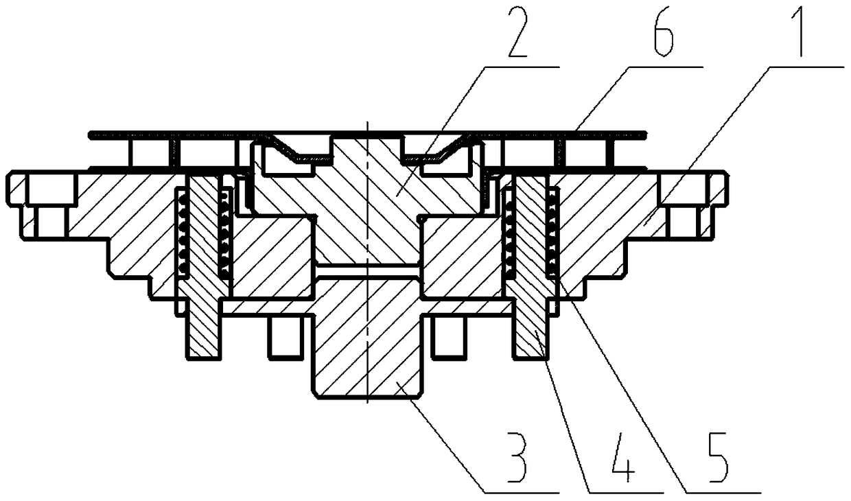
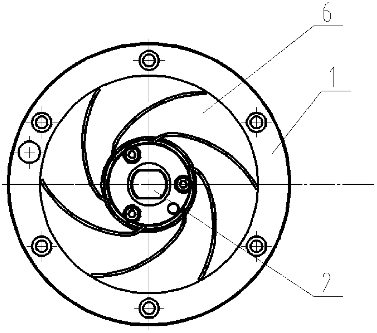
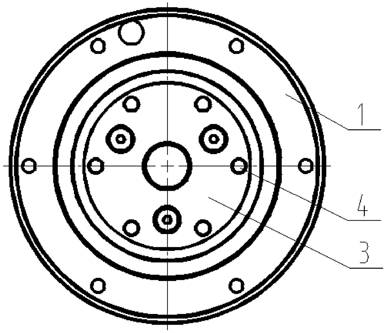
[0018] see figure 1 - Figure 5 , an impeller welding jig with mold groove positioning and auxiliary blanking function of the present invention, its principle is to position the impeller with the mold groove, and the mode of external force to push the spring top material to assist blanking, the welding fixture is used for welding the B surface of the impeller, It includes a base, a central shaft, a compression spring, an ejector pin, and a fixture cover. There is a notch on the base, which matches with the notch at the lower end of the central shaft. The matching mold groove is used to position the blades. At the same time, the upper end of the central shaft is provided with a stop for positioning the rear cover. The lower end is coaxial with the upper end. The ejector pin is installed in the base, and the ejector pin is sleeved with ...


PUM


Abstract

The invention relates to a die cavity locating welding jig with an auxiliary blanking function for an impeller and a control method. The die cavity locating welding jig comprises a base, a central shaft, a compression spring, a top pin and a clamp cover plate; the base is provided with a seam allowance which is matched with another seam allowance in the lower end of the central shaft, the central shaft is mounted on the base, the central shaft is provided with a plurality of die cavities matched with a blade, the upper end of the central shaft is provided with a seam allowance for locating a rear cover plate, the seam allowance in the lower end and the seam allowance in the lower end are coaxial, the top pin is mounted in the base, the compression spring sleeves the top pin, the clamp cover plate is mounted on the base, the top pin is used in a blanking position to push out a workpiece, the compression spring plays a resetting role of the top pin, a semi-finished product of which A surface welding of the impeller has been finished is placed in the die cavity of the central shaft, the upper surface of the base and an impeller semi-finished product are flatly attached, and the rear cover plate is placed in an upper end opening of the central shaft to finish workpiece clamping. The die cavity locating welding jig is simple, easy and fast in clamping and precise in location, reliable in welding quality, high in surface smoothness, high in production efficiency and low in labor intensity and has zero rejection rate.

Description

technical field [0001] The invention relates to a welding device. In particular, it relates to an impeller welding jig with mold groove positioning and auxiliary blanking function. The invention also relates to a control method for an impeller welding jig with a cavity positioning belt and an auxiliary blanking function. Background technique [0002] In the prior art, there are manual welding, laser welding, etc. for the welding of the impeller, but the welding efficiency is low, the labor intensity is low, the welding quality is low, the weld seam is not beautiful, and the scrap rate is high, which increases the production cost and reduces the production efficiency. Contents of the invention [0003] The object of the present invention is to provide an impeller welding jig with mold groove positioning and auxiliary blanking function, which has precise positioning, reliable welding and high efficiency. The object of the present invention is also to provide a method for c...

Claims


Application Information

Patent Timeline
Patent Type & Authority Patents(China)
IPC IPC(8): B23K37/04B23K37/00
CPCB23K37/00B23K37/0443
Inventor 周钢彭琦明刘斌
Owner WUHAN CHUTIAN IND LASER EQUIP
Learn More