
Automatic wiping mechanism and light sorting equipment provided with same

An automatic wiping and spectroscopic technology, applied in the direction of sorting, cleaning methods using gas flow, chemical instruments and methods, etc., can solve the problems of low cleaning efficiency, cumbersome process, high cost, etc., and achieve high automation, high cleaning efficiency, high substitution effect

Active Publication Date: 2017-06-20
SHENZHEN HI TEST SEMICON EQUIP
View PDF7 Cites 5 Cited by
  • Summary
  • Abstract
  • Description
  • Claims
  • Application Information

AI Technical Summary

Problems solved by technology

Among them, the component clamping method, the material is placed in the suction nozzle slot of the turntable, and the side pins of the component are used for testing during the test. The clamping test method has limitations, and the component without pins on the side cannot be tested.
The other is the pin test method at the bottom of the component. Before the test, first debug to ensure that the test needle is aligned with the position of the turntable suction nozzle to pass through the needle hole, so as to avoid the deviation causing needle breakage. During the test, the test needle must pass through the turntable suction nozzle, and the test action time The time for the test needle to completely leave the turntable must be added. This test method is difficult to debug and operate, with low efficiency, short probe life and high cost.
In addition, during the production process of spectroscopic equipment, the transparent turntable is often contaminated by dust and other debris, which will affect the detection; and when cleaning, it needs to be disassembled to clean, the process is cumbersome, and the cleaning efficiency is low

Method used


Image

  • Automatic wiping mechanism and light sorting equipment provided with same
  • Automatic wiping mechanism and light sorting equipment provided with same
  • Automatic wiping mechanism and light sorting equipment provided with same

Examples


Embodiment Construction

[0032] In order to fully understand the technical content of the present invention, the technical solutions of the present invention will be further introduced and illustrated below in conjunction with specific examples, but not limited thereto.

[0033] Such as Figure 1 to Figure 13 Shown is a specific structural view of this embodiment.

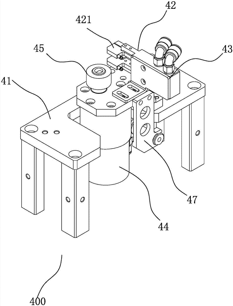
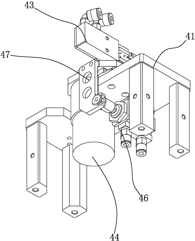
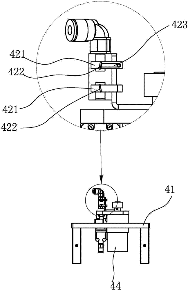
[0034] Figure 1 to Figure 3 As shown, an automatic wiping mechanism 400 includes a fixing frame 41 and a wiping assembly 42 slidably coupled to the fixing frame 41 . The wiping assembly 42 is provided with a wiping block 421 for wiping the transparent turntable 23 . The wiping block 421 is provided with a scraper 422 directly in contact with the transparent turntable 23 . The scraper 422 forms an inclination angle of 20°-90° with the moving direction of the transparent turntable 23 .

[0035] There are at least two wiper blocks 421, which are arranged opposite to each other. The wiping block 421 is disposed on the clamping power memb...


PUM


Abstract

The invention discloses an automatic wiping mechanism and light sorting equipment provided with same. The automatic wiping mechanism comprises a fixing bracket and a wiping assembly, wherein the wiping assembly is linked to the fixing bracket in a sliding manner. The wiping assembly is provided with wiping blocks used for wiping a to-be-cleaned plate. Each wiping block is provided with a scraping piece which is in direct contact with the to-be-cleaned plate. An inclination angle with the degree being 20-90 is formed between each scraping piece and the movement direction of the to-be-cleaned plate. By means of the automatic wiping mechanism arranged below, the surface of a transparent rotating disc is wiped to be clean. The transparent rotating disc is driven by a rotating power component and wiped and cleaned through the wiping blocks, and waste collected in the wiping process is sucked away through ash sucking chambers linked with a vacuum air source. The light sorting equipment provided with the automatic wiping mechanism is high in automation degree and cleaning efficiency; cleaning can be conducted without demounting the transparent rotating disc; and the cleaning mode is simple, fast and convenient. By means of the automatic wiping mechanism, the transparent rotating disc can be cleaned in time, and a detected electronic element can be high in precision and efficiency.

Description

technical field [0001] The invention relates to the technical field of electronic device testing equipment, and more specifically refers to an automatic wiping mechanism and its spectroscopic equipment. Background technique [0002] The spectrometer is one of the indispensable equipment for the production of LEDs. It is used to classify and screen LEDs according to the wavelength (color), light intensity, and current and voltage of the emitted light. [0003] The turntable part is one of the main mechanisms of the spectrometer, which carries the testing process of electronic components, and undertakes the action flow of each main functional module of the equipment and the hierarchical relationship between each input and output. The main functional mechanisms form a sequential relationship around the turntable station. Complete the actions one by one. [0004] The test part of the component is the pin part, generally there are pins on the bottom surface, and the pins of some...

Claims


Application Information

Patent Timeline
Patent Type & Authority Applications(China)
IPC IPC(8): B08B1/02B08B1/00B08B5/04B07C5/342B07C5/344
CPCB07C5/342B07C5/344B08B5/043B08B1/143B08B1/20
Inventor 卓维煌刘骏蔡建镁齐建
Owner SHENZHEN HI TEST SEMICON EQUIP
Learn More