Laser light source junction box of dynamic image detection system for EMU operation fault
A technology of running failure and dynamic image, applied in the direction of cabinet/cabinet/drawer parts, modification with gaseous coolant, cooling/ventilation/heating modification, etc., can solve the problem of unfavorable sealing and heat insulation, no self-contained light source , poor shock absorption effect, etc., to achieve the effect of good waterproof function, good light source brightness and stability, and long service life
- Summary
- Abstract
- Description
- Claims
- Application Information
AI Technical Summary
Problems solved by technology
Method used
Image
Examples
Embodiment 1
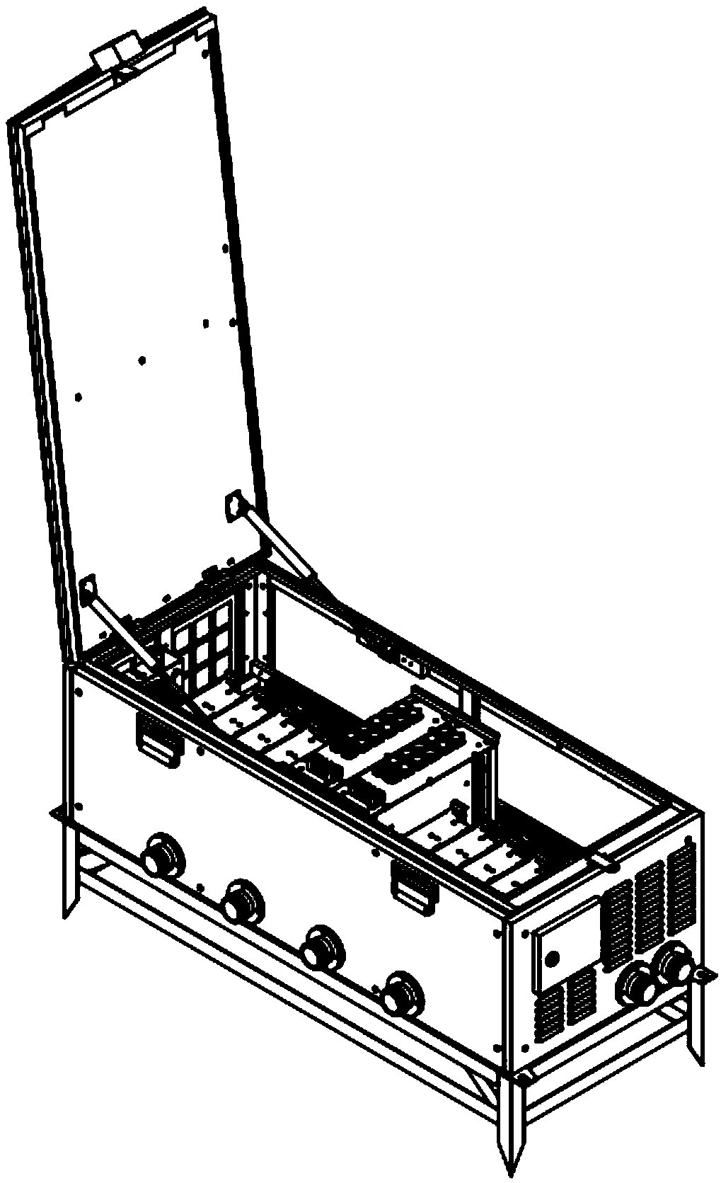
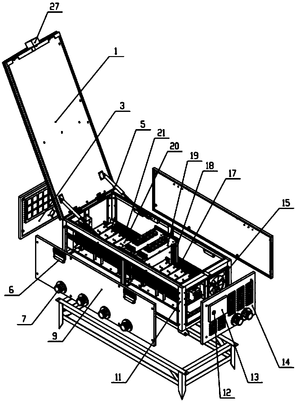
[0060] figure 1 , figure 2 , Figure 4 As shown, a laser light source junction box for a dynamic image detection system for an EMU operation fault, the laser light source junction box for a dynamic image detection system for an EMU operation fault includes: a main frame 11 of the junction box, an upper cover plate 1, and a side plate 9 , front panel 14, rear panel 3, control box;
[0061] The main frame 11 of the junction box is square, and the upper cover 1 is installed on the upper side of the main frame 11 of the junction box, and the rear side of the upper cover 1 is hinged on the main frame 11 of the junction box, and the left and right sides are equipped with The hydraulic rod 5 is connected to the main frame 11 of the distribution box through the hydraulic rod 5. The hydraulic rod 5 and the upper cover 1 of the main frame 11 of the distribution box are fixedly connected by screws, so that the upper cover 1 can be opened and fixed at a certain angle ;
[0062] The u...
Embodiment 2
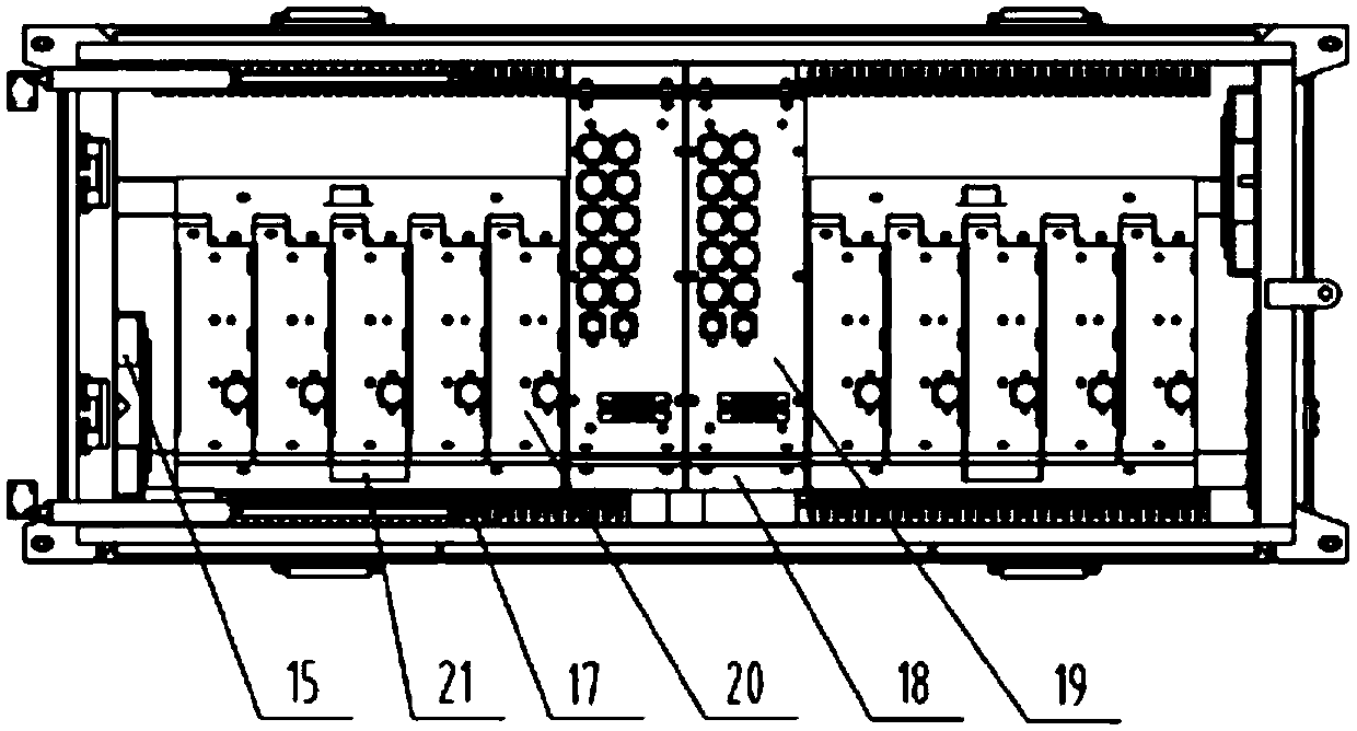
[0073] On the basis of Example 1, such as image 3 , Figure 6 to Figure 13 As shown, two sets of laser light source module fixing frames 21 and two sets of switching power supply module fixing frames 18 are mounted on the main frame 11 of the junction box through screws;
[0074] Five laser light source modules 20 are mounted on each laser light source module fixing frame 21 by screws, and one switching power supply module 19 is installed on each switching power supply module fixing frame 18 by screws;
[0075] The bottom plate of each laser light source module fixing frame 21 is provided with 10 identical foot pad holes, and each laser light source module 20 lower end is equipped with 2 identical foot pads 26, and the foot pads 26 can be snapped into the foot pad holes. When the laser light source module 20 is loaded into the laser light source module fixing frame 21, the foot pad 26 is snapped into the foot pad hole, which reduces the vibration of the laser light source mo...
Embodiment 3
[0078] On the basis of embodiment 1 or implementation 2, such as figure 2 , Figure 4 , Figure 5 , Figure 14 As shown, each laser light source module 20 is provided with a thermistor.
[0079] A door lock 12 is provided on the control box door 13, and the control box can be operated after opening the door lock 12; a guide rail 23 is provided in the control box, and the guide rail 23 is connected and fixed with the main frame 11 of the junction box by screws;
[0080] An air switch 24 and a three-phase socket 25 are mounted on the guide rail 23 by screws.
[0081] An LED light strip 28 is installed above the inner side of the junction box main body frame 11, and the LED light strip 28 realizes lighting, which is convenient for the operator to install and overhaul; With lighting off, energy saving and environmental protection;
[0082] The upper cover 1 is provided with a wrench, and the switch of the LED light strip 28 is set at the wrench, and when the upper cover 1 is...
PUM
 Abstract
Description
Claims
Application Information
 - Generate Ideas
- Intellectual Property
- Life Sciences
- Materials
- Tech Scout
- Unparalleled Data Quality
- Higher Quality Content
- 60% Fewer Hallucinations
Browse by: Latest US Patents, China's latest patents, Technical Efficacy Thesaurus, Application Domain, Technology Topic, Popular Technical Reports.
© 2025 PatSnap. All rights reserved.Legal|Privacy policy|Modern Slavery Act Transparency Statement|Sitemap|About US| Contact US: help@patsnap.com


