


Quick Research
Generate reliable direction feasibility study reports for your R&D in just a few steps.

Technical Q&A
Discover and master advanced knowledge NOW. Basics, ideas, possibilities, all at once.

Find Solutions
As an expert in R&D theories, this can generate solutions to your technical problems instantly.

Evaluate Feasibility
Analyze your overall solution with one click, know your potential R&D risks in advance.

Monitor Landscape
Get weekly tech updates, stay abreast of the latest tech innovations and key insights.
Zero-ohm resistance-based high-reliability LED (Light Emitting Diode) lamp bead
A technology of LED lamp beads and ohmic resistors, applied in circuits, electrical components, electric solid devices, etc., can solve the problems of damaged lamp quality, current aging, weakened luminous intensity, etc. The effect of service life
- Summary
- Abstract
- Description
- Claims
- Application Information
AI Technical Summary
Problems solved by technology
Method used
Image

Examples
Embodiment 1
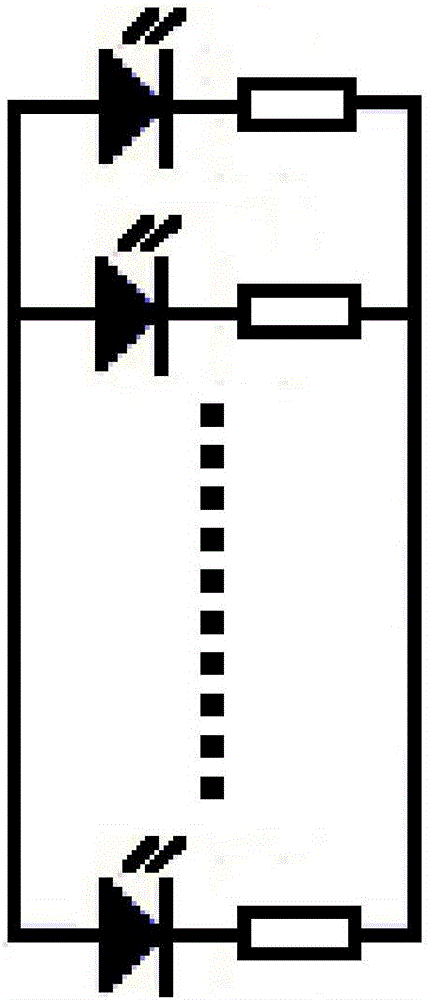
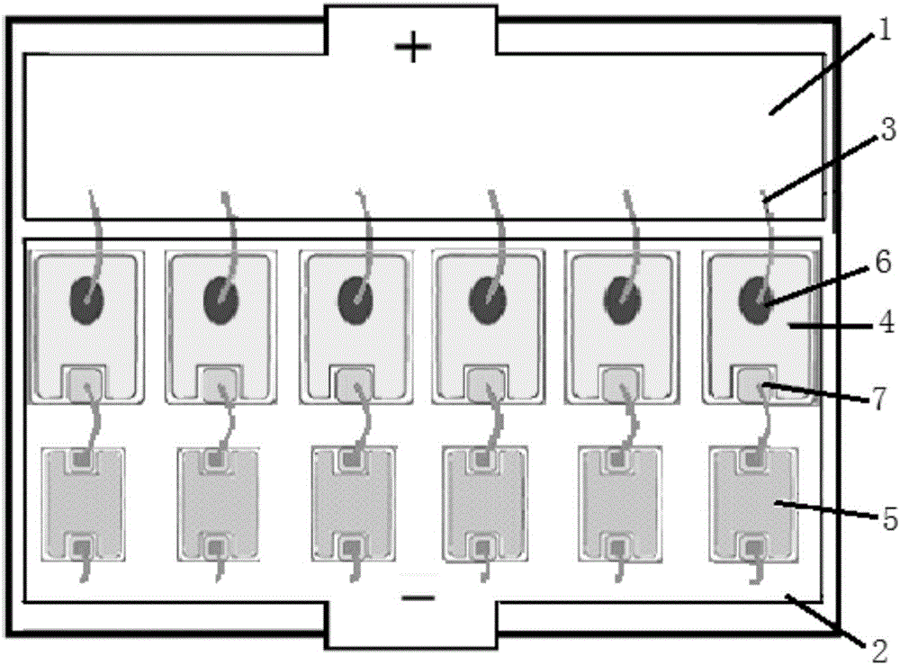
[0024] A high-reliability LED lamp bead based on zero-ohm resistance, such as figure 2 As shown, it includes 6 light-emitting units connected in parallel, each light-emitting unit includes an LED chip and a zero-ohm resistor, and the LED chip and the zero-ohm resistor are connected in series with gold wires. Gold wires are used to connect the positive electrode of the light-emitting unit to the P-type electrode of the LED chip, between the N-type electrode of the LED chip and the zero-ohm resistor, and between the zero-ohm resistor and the negative electrode of the light-emitting unit. If an LED chip in the lamp bead fails and short-circuits, all the current of the lamp bead will flow into the failed LED chip, and the current is far greater than the rated current of the LED chip. At this time, the current flowing through the light-emitting unit will It will burn off the zero-ohm resistor or gold wire connected in series with the LED chip, making the light-emitting unit form a...
Embodiment 2
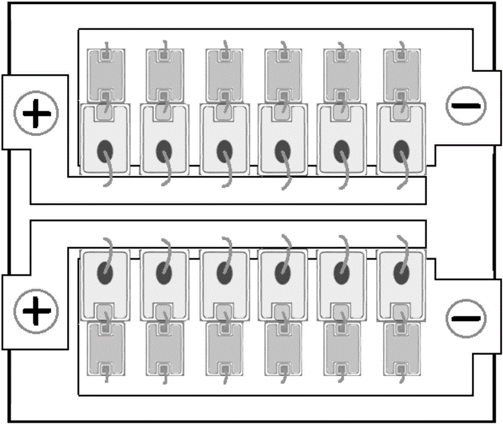
[0026] A high-reliability LED lamp bead based on zero-ohm resistance, such as image 3 As shown, it includes 12 light-emitting units. The above-mentioned 12 light-emitting units are divided into two light-emitting groups. Each light-emitting group includes 6 light-emitting units. The 6 light-emitting units in the light-emitting group are connected in parallel, and then the light-emitting groups are connected in parallel. . Wherein, each light-emitting unit includes an LED chip and a zero-ohm resistor, and the LED chip and the zero-ohm resistor are connected in series with gold wires. Gold wires are used to connect the positive electrode of the light-emitting unit to the P-type electrode of the LED chip, between the N-type electrode of the LED chip and the zero-ohm resistor, and between the zero-ohm resistor and the negative electrode of the light-emitting unit. Dividing the 12 light-emitting units into two light-emitting groups and then connecting them in parallel can effecti...
PUM
 Abstract
Description
Claims
Application Information
 - R&D Engineer
- R&D Manager
- IP Professional
- Industry Leading Data Capabilities
- Powerful AI technology
- Patent DNA Extraction
Browse by: Latest US Patents, China's latest patents, Technical Efficacy Thesaurus, Application Domain, Technology Topic, Popular Technical Reports.
© 2024 PatSnap. All rights reserved.Legal|Privacy policy|Modern Slavery Act Transparency Statement|Sitemap|About US| Contact US: help@patsnap.com