Mixed light dispersion type light source

A diffused and light-mixing technology, which is applied to light sources, semiconductor devices of light-emitting elements, and loss prevention measures of lighting devices, etc. The effect of high angle, finished product qualification rate and reduced process difficulty

Inactive Publication Date: 2016-10-26
亚浦耳照明股份有限公司
View PDF11 Cites 0 Cited by
  • Summary
  • Abstract
  • Description
  • Claims
  • Application Information

AI Technical Summary

Problems solved by technology

This method of adding lenses is achieved by adding a separate lens to each lamp bead, which has large limitations and tends to lead to a single product and is difficult to diversify
In addition, in order to ensure that the light does not deform, each lens needs to be accurately aligned with the corresponding lamp bead, the preparation process is complicated and difficult to control; the qualified rate of the finished product is low
[0004] With the further development of LED products, in order to solve the complex process and poor pass rate caused by each lamp bead equipped with a lens, some technicians use multiple light sources to connect single lenses together to form a lens module
However, this method does not fundamentally solve the problem of changing the light pattern after the position deviation of the lamp beads; in addition, the number of lenses must be consistent with the number of lamp beads, which leads to great limitations in design and production
[0005] Therefore, there is a need for an LED product that can solve the problems of small light-emitting angle and small irradiation area of ​​LED lamp beads; difficult lens production and complicated process; deviation of the light source of the lens connection module, difficult process, and large design limitations.

Method used


Image

  • Mixed light dispersion type light source
  • Mixed light dispersion type light source
  • Mixed light dispersion type light source

Examples


Embodiment Construction

[0027] The following disclosure provides many different embodiments or examples for implementing different structures of the present invention. To simplify the disclosure of the present invention, components and arrangements of specific examples are described below. Furthermore, the present invention may repeat reference numerals and / or letters in different instances. This repetition is for the purpose of simplicity and clarity and does not in itself indicate a relationship between the various embodiments and / or arrangements discussed. It should be noted that components illustrated in the figures are not necessarily drawn to scale. Descriptions of well-known components and processing techniques and processes are omitted herein to avoid unnecessarily limiting the present invention.

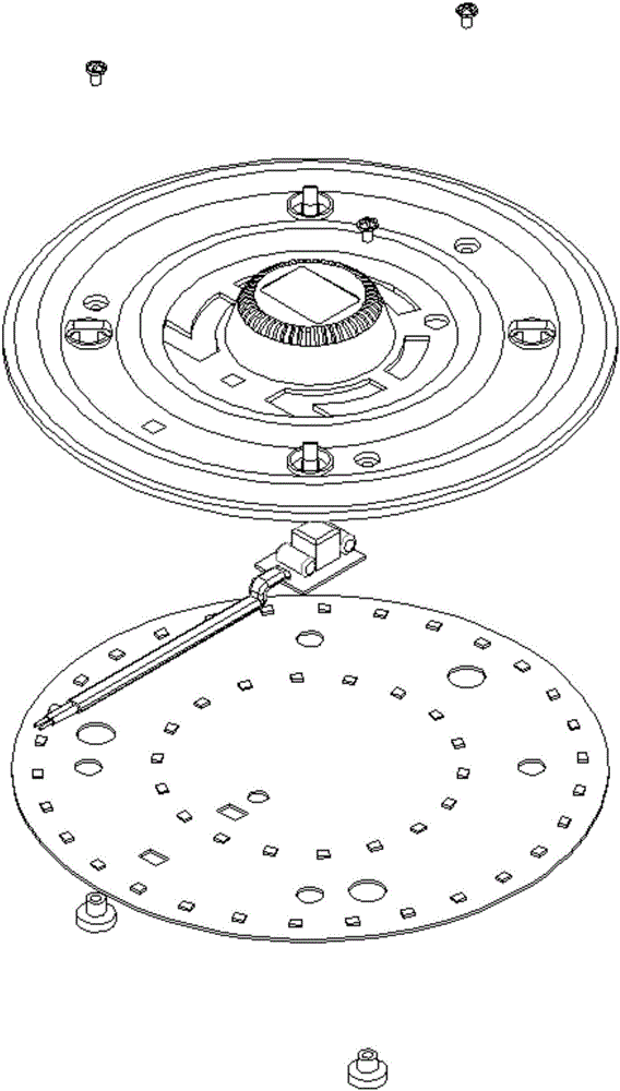
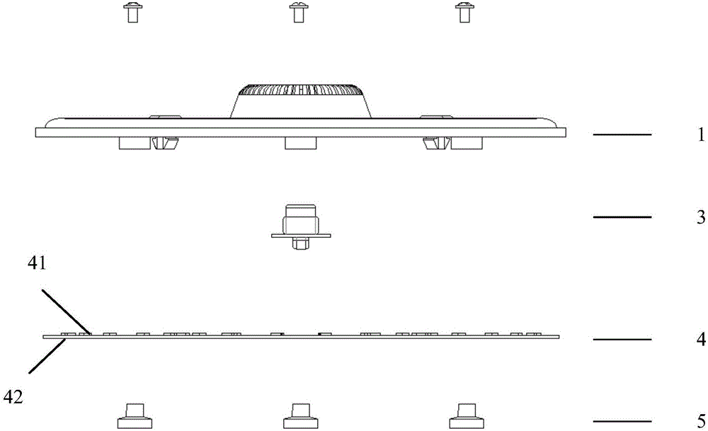
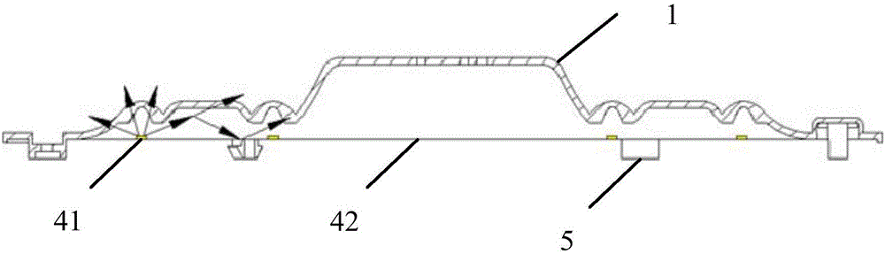
[0028] see figure 1 and figure 2 , The light mixing and diffusing light source provided by the present invention includes: a light mixing and diffusing cover 1 , a driving power supply 3 and a...


PUM

PropertyMeasurementUnit
Thicknessaaaaaaaaaa
Thicknessaaaaaaaaaa
Thicknessaaaaaaaaaa

Abstract

The invention discloses a mixed light dispersion type light source. The mixed light dispersion type light source comprises a mixed light dispersion cover, a driving power supply machine and a light emitting body; the light emitting body includes a light source carrier and a light source; the light source is arranged on the light source carrier; the driving power supply machine is fixed above the light emitting body; the mixed light dispersion cover covers the light emitting body; the mixed light dispersion cover has a cavity matched with the driving power supply machine for protecting the driving power supply machine; and the mixed light dispersion cover is provided with multiple grooves and / or projections concentric with the mixed light dispersion cover and parallel to the edge of the mixed light dispersion cover. The mixed light dispersion type light source, provided by the invention, is simple in process, easy to realize, high in pass percent of finished products and excellent in light emitting effect.

Description

technical field [0001] The invention belongs to the technical field of LED lighting, and in particular relates to a light mixing and diffusing light source. Background technique [0002] With the continuous innovation of LED lighting technology, the application range of LED products is becoming wider and wider. However, due to the strong directivity of LED light, the light-emitting area of ​​LED products is small. This defect hinders the further development of LED lighting products. [0003] In many existing LED products, a lens is added to the LED light source, and the light emitted by the LED light source is diffused through the lens, so as to increase the light-emitting angle of the LED product. This method of adding lenses is realized by adding a separate lens to each lamp bead, which has large limitations and tends to lead to a single product and is difficult to diversify. In addition, in order to ensure that the light does not deform, each lens needs to be accurately...

Claims


Application Information

Patent Timeline
IPC IPC(8): F21V3/02F21V5/00F21V15/00F21Y115/10
CPCF21V3/02F21V5/00F21V15/00
Inventor 黄晋
Owner 亚浦耳照明股份有限公司
Why Eureka
Try Eureka