Transverse test device and method for duct piece joint
A technology for segment joint and bending test, applied in the field of inspection, can solve problems such as unreliable test results and limited adaptability, and achieve the effects of accurate segment data collection, expansion of adaptability, and improvement of accuracy
Inactive Publication Date: 2017-06-13
上海盾构设计试验研究中心有限公司 +1
View PDF5 Cites 3 Cited by
- Summary
- Abstract
- Description
- Claims
- Application Information
AI Technical Summary
Problems solved by technology
[0004] The technical problem to be solved by the present invention is to provide a bending test device and method for segment joints by overcoming the unreliable test results and limited adaptability of the existing segment joint bending test device. The method realizes the bending moment loading, and realizes the c
Method used
View moreImage
Smart ImageViewing Examples
Examples
 PUM
 Abstract
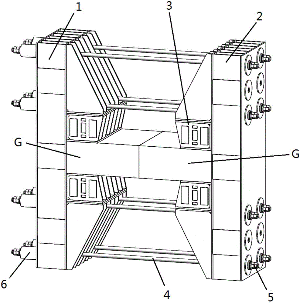
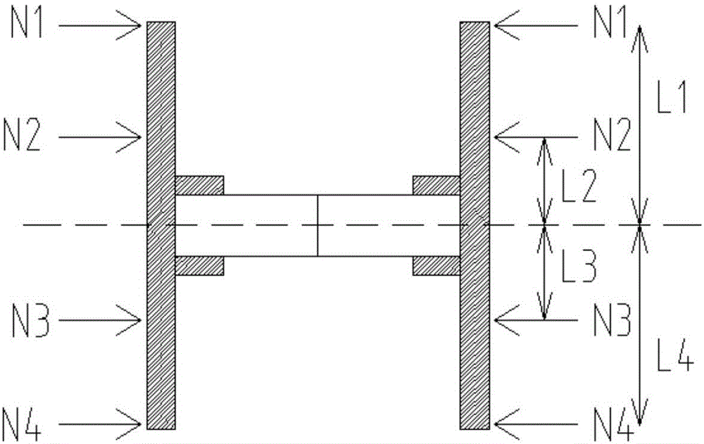
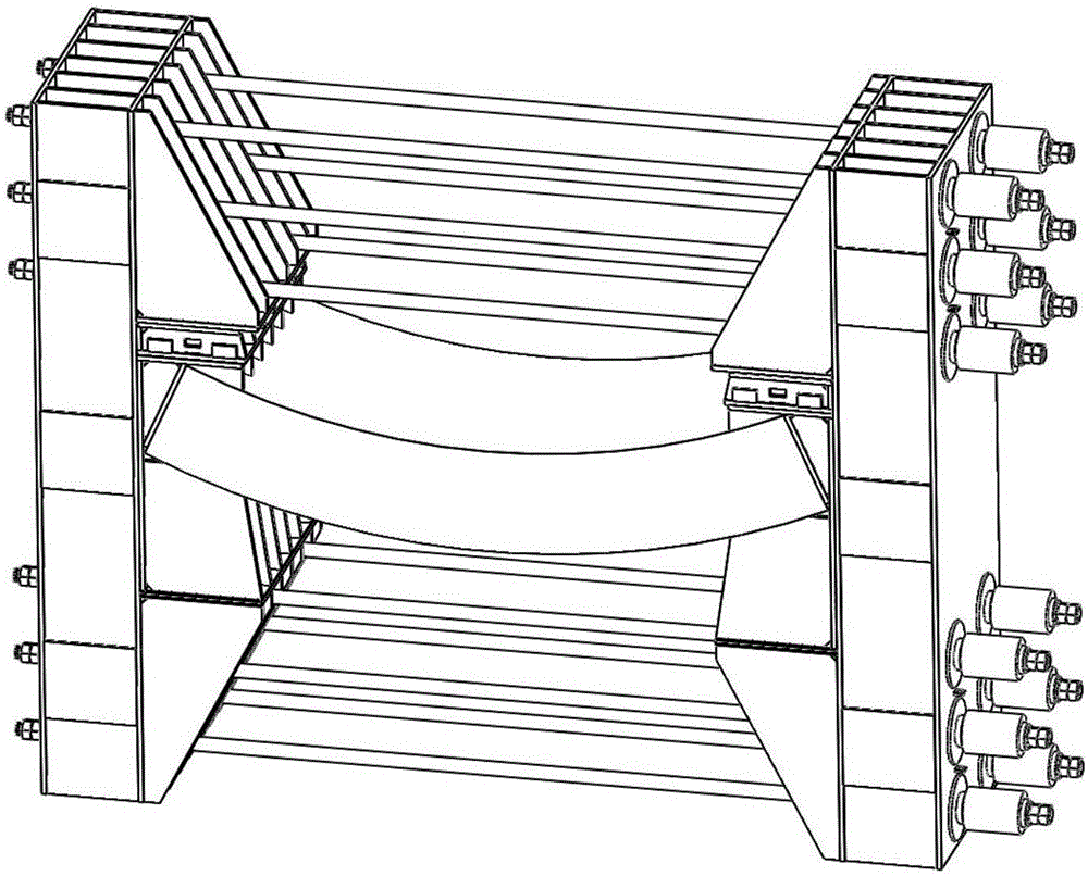
The invention relates to a transverse test device for a duct piece joint, comprising a left counter-force frame, a right counter-force frame, padding cushion blocks, multiple sets of force applying mechanisms, a hydraulic loading system and an electrical control system, wherein the left counter-force frame and the right counter-force frame are oppositely arranged and have same symmetrical structures; the padding cushion blocks are respectively plugged at two sides of the duct piece joint and between the left counter-force frame and the right counter-force frame; the duct piece joint is fixedly clamped between the left counter-force frame and the right counter-force frame; the multiple sets of force applying mechanisms are distributed on two sides of the duct piece joint to connect the left counter-force frame and the right counter-force frame and apply inward lengthways tension; the multiple sets of force applying mechanisms are controlled by the hydraulic loading system and the electrical control system to carry out loading on the left counter-force frame and the right counter-force frame to form a bending moment at the duct piece joint as shown in a formula of the description, wherein Ni is lengthways tension of various force applying mechanisms; Li is a transverse distance between all the force applying mechanisms and the duct piece joint; and I is the number of the force applying mechanisms. The transverse test device for the duct piece joint has the advantages of simple structure, strong adaptability and high accuracy, is suitable for duct piece joint transverse tests of various duct pieces in various working conditions, and is particularly qualified for the transverse test of the duct piece joint with a large bending moment.
Description
technical field [0001] The invention relates to a mechanical performance test device, in particular to a bending resistance test device and method for segment joints, belonging to the technical field of detection. Background technique [0002] In tunnel engineering, the prototype size of the actual engineering and structure is generally large and complex, and its mechanical properties and stress mechanism cannot be obtained through direct research on the structure, but model tests must be used, that is: with the help of models, based on similar The principle and similarity criteria are tested to obtain various data and performance of the structure, and provide test basis for the design and construction of the tunnel. During the construction of the tunnel structure, there are segment joints due to the structure and construction technology. There are many ways to connect the segment joints, such as bolt joints, joints without connectors, plug-in joints, pin-insert joints and s...
Claims
Login to View More Application Information
Patent Timeline
 IPC IPC(8): G01N3/20
CPCG01N3/20G01N2203/0023
Inventor 庄欠伟张弛杨正
Owner 上海盾构设计试验研究中心有限公司
Features
- R&D
- Intellectual Property
- Life Sciences
- Materials
- Tech Scout
- Unparalleled Data Quality
- Higher Quality Content
- 60% Fewer Hallucinations
Learn More Browse by: Latest US Patents, China's latest patents, Technical Efficacy Thesaurus, Application Domain, Technology Topic, Popular Technical Reports.
© 2025 PatSnap. All rights reserved.Legal|Privacy policy|Modern Slavery Act Transparency Statement|Sitemap|About US| Contact US: help@patsnap.com


