
Traction equipment

A technology of traction equipment and drawbar, which is applied in the field of railway vehicle test equipment, can solve the problem that the critical speed of vehicle instability cannot be accurately measured, and achieve the effect that the critical snaking instability speed value is real and effective

Active Publication Date: 2020-03-06
CRRC QINGDAO SIFANG ROLLING STOCK RES INST
View PDF6 Cites 0 Cited by
  • Summary
  • Abstract
  • Description
  • Claims
  • Application Information

AI Technical Summary

Problems solved by technology

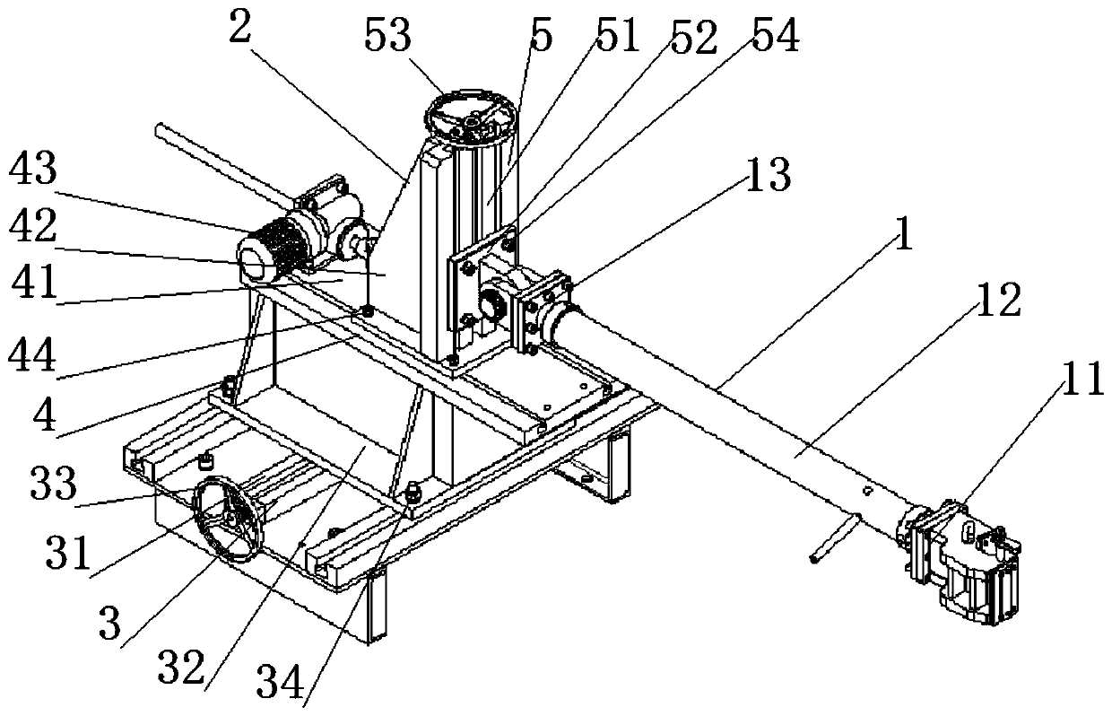
[0005] Aiming at the technical problem that the existing traction equipment cannot accurately measure the critical speed of vehicle instability, the present invention proposes a traction device that can accurately measure the critical speed of vehicle instability

Method used


Image

  • Traction equipment
  • Traction equipment
  • Traction equipment

Examples


Embodiment Construction

[0021] In the following, the present invention will be specifically described through exemplary embodiments. It should be understood, however, that elements, structures and characteristics of one embodiment may be beneficially incorporated in other embodiments without further recitation.

[0022] In the description of the present invention, it should be noted that, Figure 4 The horizontal direction shown is the longitudinal direction of the traction device of the present invention, perpendicular to Figure 4 The direction is the transverse direction of the traction equipment of the present invention, Figure 4 The vertical direction shown is the vertical direction of the traction device of the present invention; the orientation or positional relationship indicated by the terms "upper", "lower" etc. Figure 4 The positional relationship shown is only for the convenience of describing the present invention and simplifying the description, but does not indicate or imply that t...


PUM


Abstract

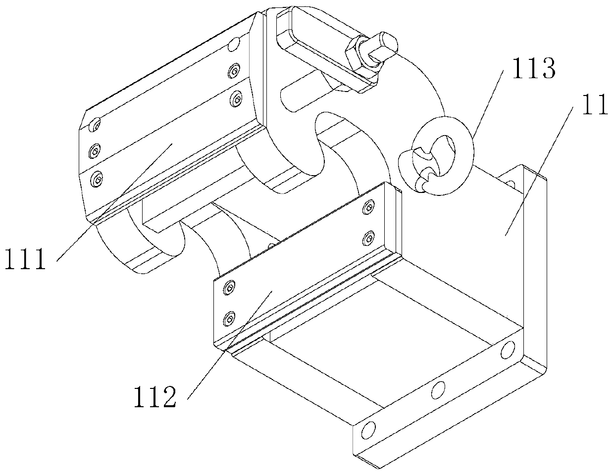
The present invention provides a traction device. The traction device is used for railway vehicle rolling test, and comprises a traction rod module, the traction rod module comprises a coupler knuckle, a traction rod having one end fixedly connected with the coupler knuckle and a connection base fixedly connected with the other end of the traction rod; the traction device also comprises a movable device capable of driving the traction rod module to rectilinear motion along three directions of degrees of freedom, the movable device comprises a horizontal adjustment module, a longitudinal adjustment module and a vertical adjustment module, and the connection base is in spherical hinging with a movable device ball. The traction device can accurately measure the unstable critical speed of a vehicle.

Description

technical field [0001] The invention belongs to the technical field of railway vehicle test equipment, and in particular relates to a traction device used for rolling test of railway vehicles. Background technique [0002] The rolling test of railway vehicles is mainly to test the critical speed of snaking instability when the vehicle is running. The results of the rolling test are very important to the safe operation of the train. During the rolling test of railway vehicles, the wheelset of the bogie runs in situ on the rolling test bench. At this time, traction equipment is required to limit the freedom of the vehicle in the longitudinal direction to prevent falling accidents. [0003] Chinese invention patent CN102435374A discloses a locomotive fixed rolling test bench traction force meter, including a traction force measuring device, a reducer and a screw, and the traction force measuring device includes a guide frame, a force sensor, a traction connecting rod, The coup...

Claims


Application Information

Patent Timeline
Patent Type & Authority Patents(China)
IPC IPC(8): G01M17/08
CPCG01M17/08
Inventor 姚宝天孟范鹏李世双武伟刘琛宝刘海燕董思冲
Owner CRRC QINGDAO SIFANG ROLLING STOCK RES INST
Learn More