
Reinforcing device for mortise and tenon joints of wooden beams and columns in ancient buildings

A reinforcement device, a technology of wooden beams and columns, applied in construction, building components, building maintenance, etc., can solve the problems of obvious damping energy consumption performance, inability to control semi-rigid characteristics of nodes and damping effect, etc., and achieve the goal of reducing the difficulty of reinforcement Effect

Active Publication Date: 2018-09-11
ANHUI UNIVERSITY OF TECHNOLOGY
View PDF6 Cites 0 Cited by
  • Summary
  • Abstract
  • Description
  • Claims
  • Application Information

AI Technical Summary

Problems solved by technology

Although there are composite joints of steel-timber structures at present, since the ancient buildings are mainly mortise and tenon joints, the mortise and tenon joints themselves are semi-rigid connections, and under the action of earthquakes, the damping energy dissipation performance is obvious
Most of the existing steel-timber structure composite nodes are hinged or rigidly connected, which cannot control the semi-rigid characteristics and damping effect of the joint rotation. Torsional Effects Under Earthquake Action

Method used


Image

  • Reinforcing device for mortise and tenon joints of wooden beams and columns in ancient buildings
  • Reinforcing device for mortise and tenon joints of wooden beams and columns in ancient buildings
  • Reinforcing device for mortise and tenon joints of wooden beams and columns in ancient buildings

Examples


Embodiment Construction

[0032] The following will clearly and completely describe the technical solutions in the embodiments of the present invention with reference to the accompanying drawings in the embodiments of the present invention. Obviously, the described embodiments are only some, not all, embodiments of the present invention. Based on the embodiments of the present invention, all other embodiments obtained by persons of ordinary skill in the art without creative efforts fall within the protection scope of the present invention.

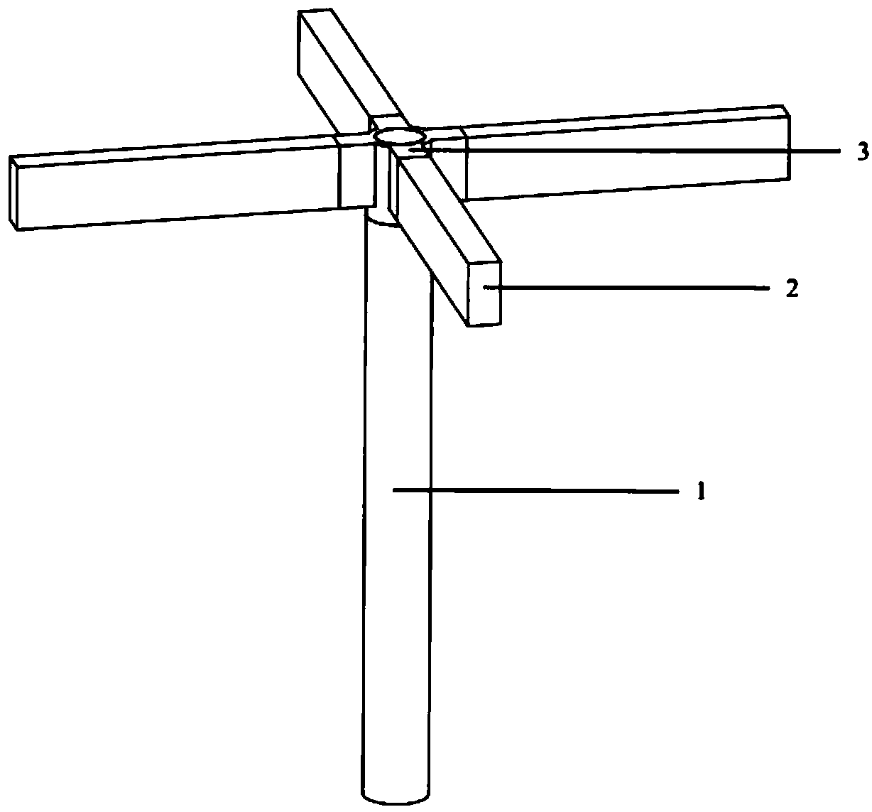
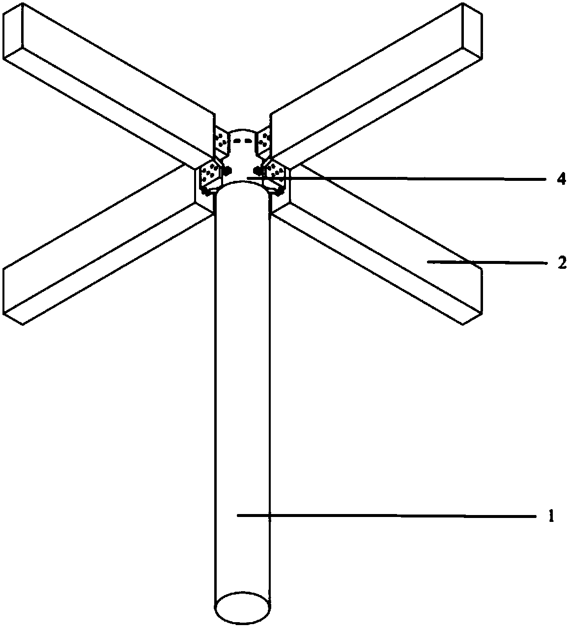
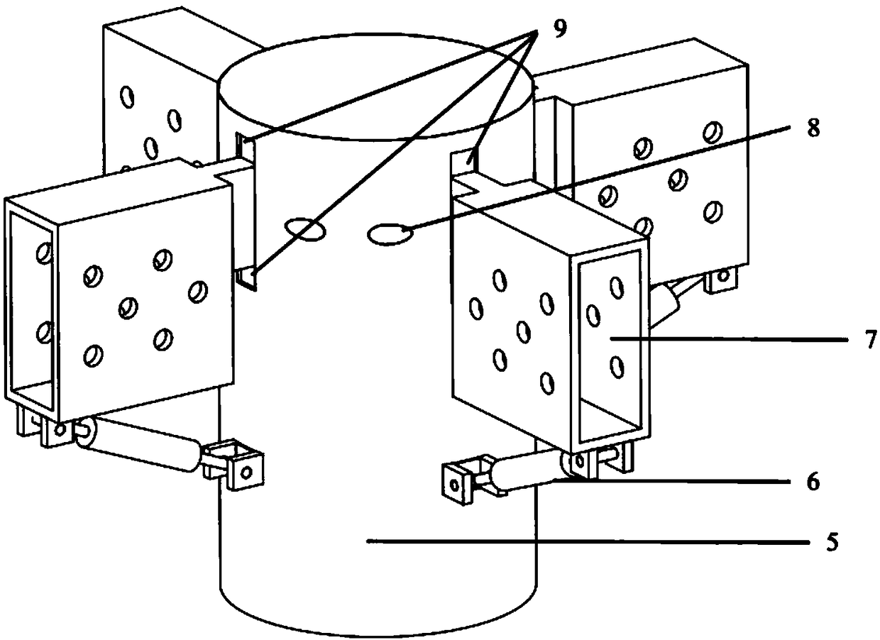
[0033] see Figure 1-12 As shown, this embodiment is a reinforcement device for wooden beams and tenon joints of ancient buildings, including a wooden column 1, a wooden beam 2 and a steel node 4, the top of the wooden column 1 is connected to the wooden beam 2 through the steel node 4, and the steel node 4. It is composed of steel node body 5, damper 6, beam connector 7, pin 8, stiffness adjustment pad 9 and interlayer board 10. Steel node body 5 and beam connecto...


PUM


Abstract

The invention discloses an ancient building wood beam-column mortise and tenon joint strengthening device comprising a wood column, wood beams and a steel joint. The top end of the wood column is connected with the wood beam through the steel joint. The steel joint is composed of a steel joint main body, dampers, beam connectors, pins, rigidity adjusting cushion blocks and an interlayer plate. The steel joint main body and the beam connectors are in steel mortise and wood tenon connection with the wood column and the wood beams correspondingly. The beam connectors are hinged to the steel joint main body through the pins. The upper side and the lower side of the end of each beam connector are provided with the corresponding cushion blocks correspondingly, wherein the two cushion blocks are fixed to a top cover and the interlayer plate of the steel joint main body correspondingly. The dampers are further arranged between the lower ends of the beam connectors and the steel joint main body. The two ends of each damper are hinged to the corresponding beam connector and the steel joint main body. According to the ancient building wood beam-column mortise and tenon joint strengthening device, the sizes of the rigidity adjusting cushion blocks and performance parameters of the dampers are simply replaced, so that the rigidity and damping characteristic of the steel joint are adjusted, strengthening is completed, and the torsional effect on the strengthened integral structure is avoided or reduced.

Description

technical field [0001] The invention relates to the technical field of wood structure reinforcement, in particular to a reinforcement device for mortise and tenon joints of wooden beams and columns in ancient buildings. Background technique [0002] It is difficult to strengthen the nodes of ancient wooden structures after they are damaged by corrosion, insects, and earthquakes. When the ancient wooden structure is partially damaged, it is expensive to dismantle and re-reinforce the installation in a large area, and the original conditions will inevitably be changed when the components are replaced or fiber reinforcement is used, and the torsional vibration of the structure is often caused by the inconsistency of the stiffness of the old and new nodes after reinforcement. , which weakens the earthquake resistance of wooden structures. Although there are composite joints of steel-timber structures at present, since ancient buildings are mainly mortise and tenon joints, the m...

Claims


Application Information

Patent Timeline
Patent Type & Authority Patents(China)
IPC IPC(8): E04G23/02E04B1/26E04B1/98E04H9/02
CPCE04B1/2604E04B2001/2616E04B2001/266E04B2001/2676E04G23/0218E04H9/021E04H9/023E04H9/0235E04H9/027
Inventor 张辰啸聂桂波戴君武
Owner ANHUI UNIVERSITY OF TECHNOLOGY
Learn More