Motor compensation control method for driverless vehicle

An unmanned vehicle, compensation control technology, applied in electric vehicles, control drives, control devices, etc., can solve the problems of poor system real-time responsiveness, large system resource occupation, aggravated system resource occupation, etc., to improve safety and reliability. performance, perfect safety standards, convenient and accurate control

Active Publication Date: 2017-06-13
HENAN NORMAL UNIV
View PDF5 Cites 5 Cited by
  • Summary
  • Abstract
  • Description
  • Claims
  • Application Information

AI Technical Summary

Problems solved by technology

Moreover, any kind of sensor has the possibility of signal abnormality, so the method of simply using the sensor signal to compensate cannot meet the reliability requirements of driverless cars
At the same time, since the sensor system of the unmanned vehicle will obtain a large amount of sensor data, processing these data will occupy a large amount of system resources and put forward higher requirements on the computing power of the system. occupancy, leading to poor real-time response of the system
In addition, ordinary cars are usually overhauled according to the time of purchase, but such a setting is obviously not accurate for unmanned vehicles. If they are used too frequently but not overhauled in time, resulting in greater wear and tear, it will greatly affect the control accuracy
If the sensor is used to know whether maintenance is required, then the above-mentioned problems of unreliable sensor signal and large system resource occupation will appear, so there is also an urgent need for an accurate and simple method of prompting the user for maintenance

Method used


Image

  • Motor compensation control method for driverless vehicle
  • Motor compensation control method for driverless vehicle
  • Motor compensation control method for driverless vehicle

Examples


Embodiment Construction

[0039] Describe embodiment in detail below in conjunction with accompanying drawing:

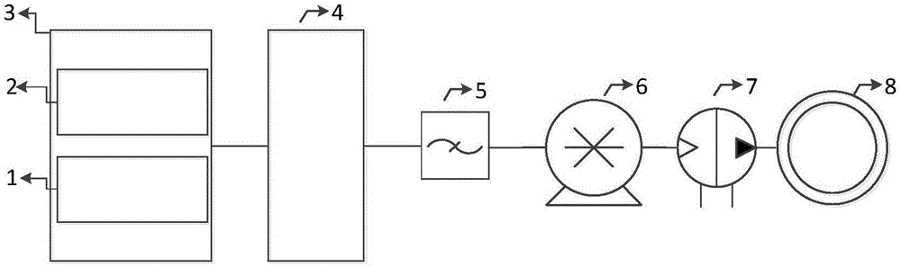
[0040] Since unmanned vehicles (referred to as unmanned vehicles) have very high requirements on safety and reliability, they need to drive precisely along the set trajectory in the unmanned state, so as to ensure the safety of driving. Usually it is easier to keep driving in a straight line, but when encountering a turn or changing lanes, it is more necessary to control the steering precisely. In the prior art, a sensor is usually used to detect the rotation angle, and a method of controlling the motor by feedback of the sensor signal is used to ensure the accuracy of the steering. However, this requires a high dependence on the accuracy and reliability of the sensor, but the sensor will inevitably fail, which can be compensated by the driver in an ordinary car, and there will be no major problems, but in an unmanned car It will lead to inaccurate steering, which will lead to traffic accid...


PUM


Abstract

A motor compensation control method for a driverless vehicle comprises: acquiring, by a controller, next turning action parameters of the vehicle according to a planned route, including turning angle u and completion time t; requesting, by the controller, to a vehicle condition database for current motor state and transmission system state; requesting, by the controller, to the vehicle condition database for determining motor compensation coefficient a according to the motor state; requesting to the vehicle condition database for determining transmission system compensation coefficient b according to the transmission system state, wherein the vehicle condition database includes an inspection-maintenance database and a delivery database, motor compensation coefficient a1 and transmission system compensation coefficient b1 in the inspection-maintenance database are updated according to latest inspection-maintenance record, and correspondence between the motor compensation system A1 and transmission system compensation coefficient B1 and the driving time in the delivery database are calibrated before delivery; a steering motor control method is modified in order to compensate steering angle deviation during autopilot, so that better autopilot effect is achieved.

Description

technical field [0001] The invention belongs to the field of motor control, in particular to the field of motor control of unmanned vehicles. Background technique [0002] In order to completely replace manual driving, unmanned vehicles need to be able to drive according to a predetermined trajectory, especially to be able to turn according to a certain curve. In driverless cars, motors are usually used to control the wheel steering, but since the driverless cars have been driving for a long time, the motors and the transmission system have certain wear and tear, making it difficult to achieve accurate steering, that is, the steering angle is different from the target angle . Although the angle can be compensated through the angle encoder, this is only one of the solutions. If the angle encoder is abnormal at the same time, the steering control cannot be performed correctly. Unlike ordinary cars, driverless cars have very high reliability requirements, so a technology that...

Claims


Application Information

Patent Timeline
Patent Type & Authority Applications(China)
IPC IPC(8): B60L15/20
CPCB60L15/20B60L2240/24B60L2240/421B60L2240/48Y02T10/72
Inventor 王立吴喜桥龚毅君
Owner HENAN NORMAL UNIV
Why Eureka
Try Eureka