Compound structure with low stress line

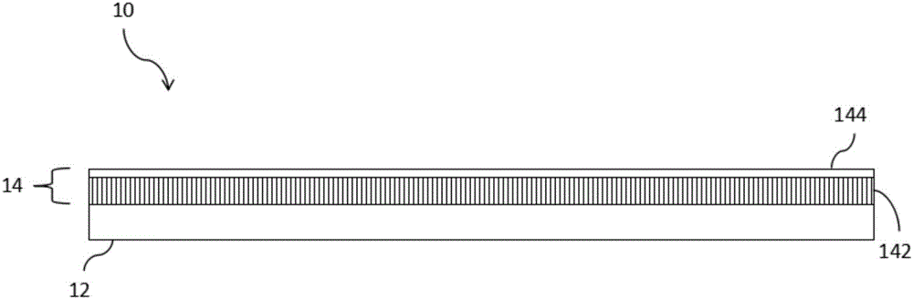
A composite structure, low stress technology, applied in the field of composite structures, can solve the problems of increased manufacturing cost, insufficient impact resistance of the cover plate structure 10, hidden safety concerns of the cover plate, etc.

Active Publication Date: 2017-06-13
INTERFACE TECH CHENGDU CO LTD +2
View PDF4 Cites 0 Cited by
  • Summary
  • Abstract
  • Description
  • Claims
  • Application Information

AI Technical Summary

Problems solved by technology

[0005] Continuing from the previous paragraph, in addition, there is also a conventional technology to change the material of the plastic injection layer 12 in order to improve the rainbow pattern, and change the original polycarbonate into acrylic to improve the generation of the rainbow pattern and reduce the stress pattern of the finished product. However, the plastic injection layer 12 using acrylic cannot be effectively combined with the bonding layer 142 using polycarbonate, so the bonding effect will be poor, or an additional bonding process will be added, resulting in increased manufacturing costs, and Concerns about the risk of bonding yield, for example, if the bonding is inadvertent, it will cause a decrease in the overall yield
Furthermore, in order to reduce rainbow lines and stress lines in some technologies, it is necessary to make the acrylic plastic injection layer 12 effectively combine with the bonding layer 142 of the composite film 14, and simply use the entire material of the composite film 14 as a pressing layer. Acrylic material, so as to eliminate the doubts of poor bonding, and does not need to increase the bonding process, but this method will lead to insufficient impact resistance of the cover structure 10, which will bring considerable security risks to the resulting cover.

Method used


Image

  • Compound structure with low stress line
  • Compound structure with low stress line
  • Compound structure with low stress line

Examples


Embodiment Construction

[0042] In order to improve the structural strength of the three-dimensional cover plate for vehicles, reduce stress lines, and bring about an economical manufacturing process, the present invention reveals an innovative cover plate structure to overcome the conventional deficiencies under the continuous research and careful study of the inventors. .

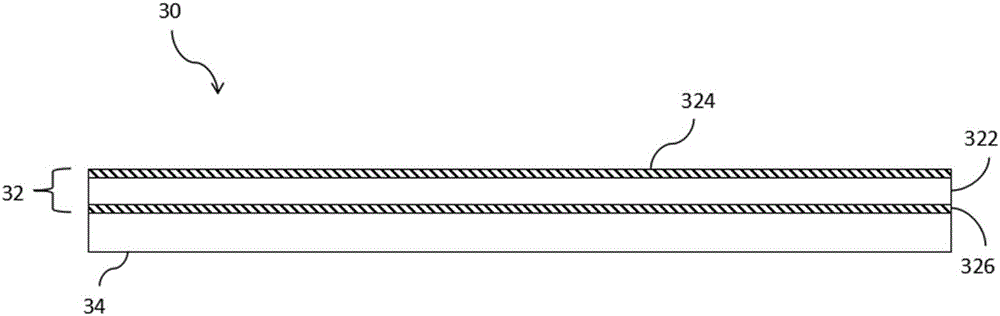
[0043] First, please refer to this invention image 3 As shown, the low-stress grain composite structure 30 of the present invention includes a composite film layer 32 and an acrylic injection layer 34 . The composite film layer 32 includes a thermoplastic material layer 322, a first acrylic hardness layer 324 and a second acrylic hardness layer 326, the thermoplastic material layer 322 has a first surface and a second surface, the first The acrylic hardness layer 324 is arranged on the first surface of the thermoplastic material layer 322, and the second acrylic hardness layer 326 is arranged on the second surface of the thermo...


PUM

PropertyMeasurementUnit
Thicknessaaaaaaaaaa
Thicknessaaaaaaaaaa

Abstract

The invention provides a compound structure with a low stress line. The compound structure comprises a compound film and an acryl ejection layer, wherein the compound film comprises a thermoplastic material layer with a first surface and a second surface; a first acryl hard layer is arranged on the first surface; a second acryl hard layer is arranged on the second surface; the acryl ejection layer is jointed with the second acryl hard layer in the manner of intra-mode forming, so that the generation of the stress line can be reduced. The compound structure with low stress line can reduce the stress line, has excellent shock resistance and is capable of providing a firm cover plate structure without a rainbow line.

Description

technical field [0001] The invention relates to a composite structure of a vehicle cover plate, in particular to a composite structure for reducing stress lines. Background technique [0002] The touch panel (Touch Panel, TP) originated from military use. After it was transferred to civilian use in the early years, the application of touch panel and the growth of technology began to produce substantial progress. Gradually, with the needs of users, touch panel It is also used in car screens as a medium for human-computer interaction. Therefore, when used in a vehicle touch panel, the cover plate must have a relatively strong hardness to withstand external impacts, thereby effectively protecting the vehicle touch panel. [0003] Continuing from the previous paragraph, in order to produce a good automotive touch panel cover, it needs to have a rainbow-resistant visual effect, the surface hardness must be strong enough, and when it is subjected to external impact, even if the i...

Claims


Application Information

Patent Timeline
IPC IPC(8): B32B27/36B32B27/08B32B27/06B32B33/00B29C47/06B29C45/16B29C45/14B60K37/00
CPCB29C45/14B29C45/16B29C48/21B29C2045/1682B32B27/08B32B27/36B32B27/365B32B33/00B32B2307/40B32B2307/536B32B2307/558B32B2457/208B32B2605/00B60K37/00
Inventor 吴景扬
Owner INTERFACE TECH CHENGDU CO LTD
Why Eureka
Try Eureka