
lighting module

A lighting module and light source technology, which is applied in the direction of lighting devices, light sources, lamp circuit layout, etc., can solve the problems of large heat generation, heat accumulation, poor heat dissipation, etc.

Active Publication Date: 2019-10-18
NINGBO SUNNY OPOTECH CO LTD
View PDF6 Cites 0 Cited by
  • Summary
  • Abstract
  • Description
  • Claims
  • Application Information

AI Technical Summary

Problems solved by technology

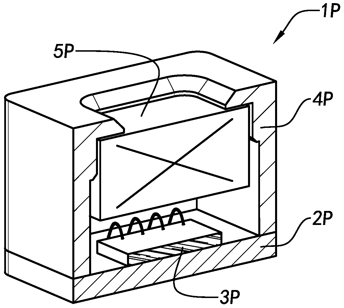
However, existing circuit boards, such as PCB boards, usually have poor heat dissipation performance, so in actual work, the heat emitted from the circuit board 2P is less, and the accumulation of heat seriously affects the circuit elements on the circuit board 2P work
[0008] Generally speaking, when the lighting module is working, the heat generation is the fundamental problem, and the poor heat dissipation effect of the corresponding matching components is an important reason for the heat accumulation. Therefore, it is necessary to start from different aspects to solve the heating problem of the lighting module

Method used


Image

  • lighting module
  • lighting module
  • lighting module

Examples


Embodiment Construction

[0050] The following description serves to disclose the present invention to enable those skilled in the art to carry out the present invention. The preferred embodiments described below are only examples, and those skilled in the art can devise other obvious variations. The basic principles of the present invention defined in the following description can be applied to other embodiments, variations, improvements, equivalents and other technical solutions without departing from the spirit and scope of the present invention.

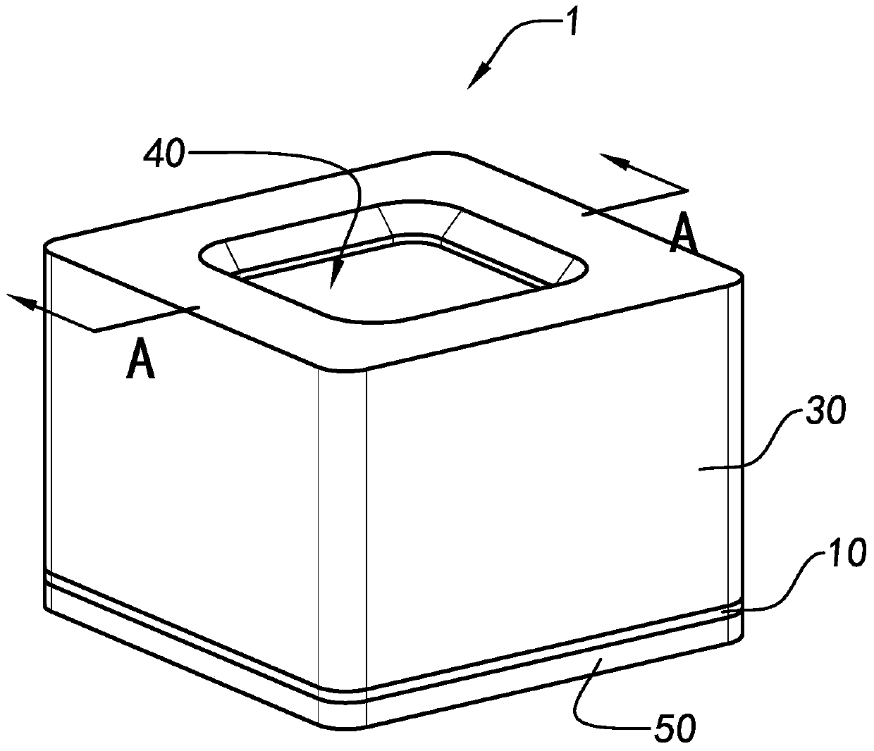
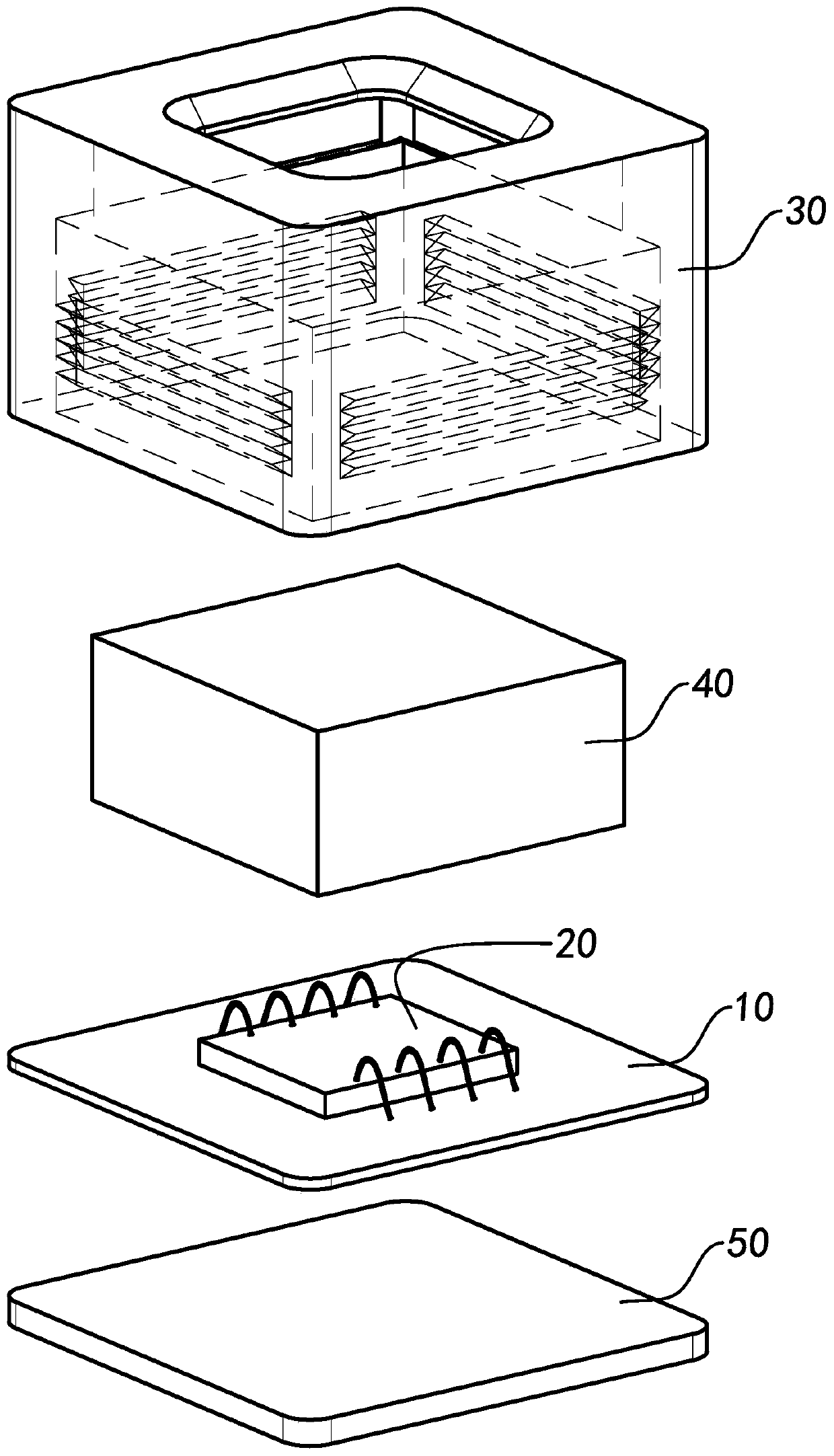
[0051] Such as Figure 2 to Figure 7 Shown is a lighting module according to a preferred embodiment of the present invention. The lighting module 1 includes a circuit board 10 , a light source chip 20 , a bracket 30 and an optical component 40 .

[0052] The light source chip 20 is arranged on the circuit board 10, the optical component 40 is installed on the bracket 30, and the bracket 30 is connected to the circuit board 10, so that the optical compon...


PUM


Abstract

The invention relates to an illumination module. The illumination module includes a circuit board, a light source chip, a support and a diffraction optical part, wherein the light source chip is arranged in the circuit board; the diffraction optical part is arranged in a microscope stand; the support is connected with the circuit board so as to enable the diffraction optical part to be above the light source chip; and the circuit board includes a work circuit which drives the light source chip to work through a pulse mode so as to reduce the heat generated from the illumination module.

Description

technical field [0001] The present invention relates to a lighting module, and further relates to a lighting module which can improve the heating problem of the lighting module. Background technique [0002] As camera modules generally enter 13M, 20M and other stages, the development of traditional CMOS modules to a higher stage has entered the bottleneck area, and how to break through the traditional imaging methods has become the current trend of the development of the intelligent imaging industry. [0003] Emerging fields such as 3D printing, 3D modeling, infrared monitoring, and iris recognition are important directions for the development and application of intelligent imaging. The lighting module is a key projection and emission source component in the field of 3D imaging. It is a laser that uses a single-point array or an array light source, and the light-emitting direction is perpendicular to the chip surface. It has the characteristics of large output power range, ...

Claims


Application Information

Patent Timeline
Patent Type & Authority Patents(China)
IPC IPC(8): H05B37/02
Inventor 卢鹏罗孟杰
Owner NINGBO SUNNY OPOTECH CO LTD
Learn More