
Tin concentrate separating system and process

A tin concentrate and process technology, applied in the field of non-ferrous metal beneficiation, can solve the problems of tin loss, heat not dissipated in time, economic loss, etc., and achieve the effects of reducing tin loss, simple structure, and high economic benefits

Inactive Publication Date: 2017-06-09
南昌专腾科技有限公司
View PDF7 Cites 2 Cited by
  • Summary
  • Abstract
  • Description
  • Claims
  • Application Information

AI Technical Summary

Problems solved by technology

It is theoretically feasible to remove sulfide (arsenic, sulfur minerals) by flotation, but in actual operation, it is often accompanied by a large loss of tin, which brings serious economic losses
In addition, there are many problems in the currently widely used rotary kiln desulphurization and arsenic removal method. The high-arsenic sulfide ore is mixed with the intermediate product slag produced in the production process, and then the arsenic and sulfur are removed at high temperature in the rotary kiln. However, some of the slag The melting point of tin-iron metal is low, and the material is agglomerated due to melting slag in the kiln. After the agglomeration, the heat is not dissipated in time. From the beginning of agglomeration to knot kiln, when the knot kiln is too thick, part of the sulfur inside does not have enough oxygen to participate in the reaction. At high temperature, sulfur and tin react to form tin sulfide, which forms a gaseous state and is sucked away with the flue gas. Tin sulfide encounters air Oxygen in the air reacts to produce sulfur dioxide and tin oxide, and the tin oxide is collected in the bag filter. Therefore, the smoke contains high tin content, generally up to 8-12%, sometimes up to 20%, roasted ore arsenic + sulfur ≤ 0.8 %

Method used


Image

  • Tin concentrate separating system and process

Examples


Embodiment 1

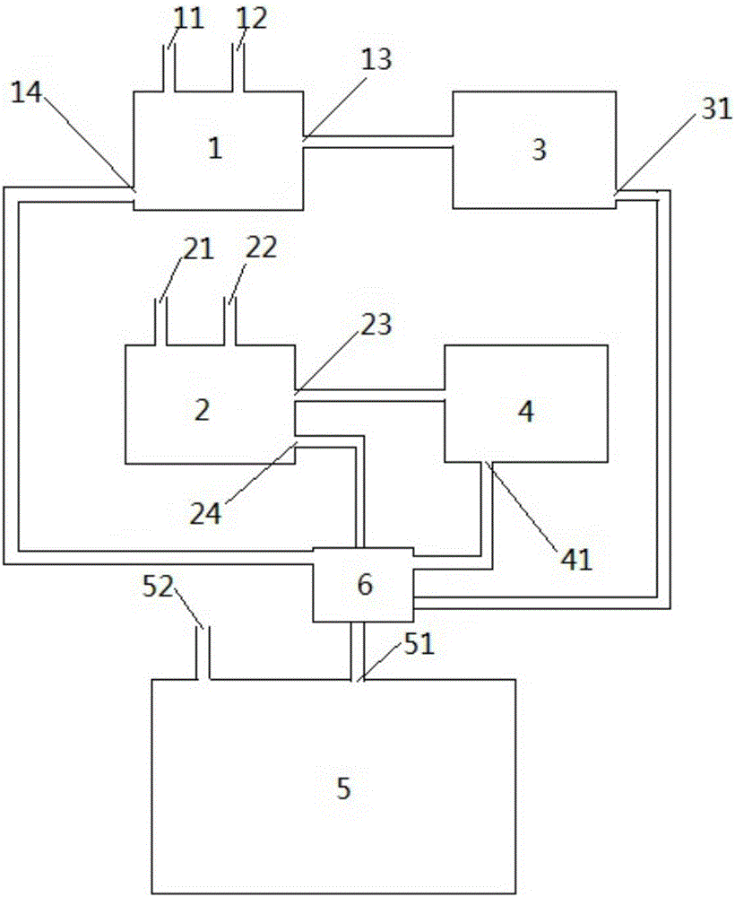
[0029] like figure 1 As shown, a tin concentrate mineral processing system includes a first flotation cell 1, a second flotation cell 2, a first rotary kiln 3, a second rotary kiln 4 and an electric furnace 5, and the electric furnace 5 is provided with a material mixture inlet 51, The material mixture inlet 51 is connected with the material mixing tank 6; the first flotation tank 1 is provided with the tin concentrate ore pulp inlet 11 and the No. 2 oil inlet 12 of styrene phosphonic acid, phenylpropanehydroxamic acid and foaming agent, the first flotation Pool 1 is also provided with a first flotation concentrate outlet 13 and a first flotation tailings outlet 14, both of which are respectively connected to the first rotary kiln 3 and the material mixing tank 6; the second flotation tank 2 is provided with a first flotation Tailings slurry inlet 21 and salicylic hydroxamic acid and foaming agent No. 2 oil inlet 22, the second flotation cell 2 is also provided with a second f...

Embodiment 2

[0045] like figure 1 As shown, a tin concentrate mineral processing system includes a first flotation cell 1, a second flotation cell 2, a first rotary kiln 3, a second rotary kiln 4 and an electric furnace 5, and the electric furnace 5 is provided with a material mixture inlet 51, The material mixture inlet 51 is connected with the material mixing tank 6; the first flotation tank 1 is provided with the tin concentrate ore pulp inlet 11 and the No. 2 oil inlet 12 of styrene phosphonic acid, phenylpropanehydroxamic acid and foaming agent, the first flotation Pool 1 is also provided with a first flotation concentrate outlet 13 and a first flotation tailings outlet 14, both of which are respectively connected to the first rotary kiln 3 and the material mixing tank 6; the second flotation tank 2 is provided with a first flotation Tailings slurry inlet 21 and salicylic hydroxamic acid and foaming agent No. 2 oil inlet 22, the second flotation cell 2 is also provided with a second f...

Embodiment 3

[0061] like figure 1 As shown, a tin concentrate mineral processing system includes a first flotation cell 1, a second flotation cell 2, a first rotary kiln 3, a second rotary kiln 4 and an electric furnace 5, and the electric furnace 5 is provided with a material mixture inlet 51, The material mixture inlet 51 is connected with the material mixing tank 6; the first flotation tank 1 is provided with the tin concentrate ore pulp inlet 11 and the No. 2 oil inlet 12 of styrene phosphonic acid, phenylpropanehydroxamic acid and foaming agent, the first flotation Pool 1 is also provided with a first flotation concentrate outlet 13 and a first flotation tailings outlet 14, both of which are respectively connected to the first rotary kiln 3 and the material mixing tank 6; the second flotation tank 2 is provided with a first flotation Tailings slurry inlet 21 and salicylic hydroxamic acid and foaming agent No. 2 oil inlet 22, the second flotation cell 2 is also provided with a second f...


PUM


Abstract

The invention discloses a tin concentrate separating system and a tin concentrate separating process. The tin concentrate separating system comprises a first floating tank, a second floating tank, a first rotary kiln, a second rotary kiln and an electric furnace; the electric furnace is provided with a material mixture inlet; the material mixture inlet is connected with a material mixing tank; a tin concentrate pulp inlet, and a styryl phosphonic acid, phenylprohydroxoxime acid and foaming agent No.2 oil inlet are formed in the first floating tank; a first floated concentrate outlet and a first floated tailing outlet are also formed in the first floating tank, and are respectively connected to the first rotary kiln and the material mixing tank; a first floated tailing pulp inlet and a salicylhydroxamic acid and foaming agent No.2 oil inlet are formed in the second floating tank; a second floated concentrated outlet and a second floated tailing outlet are also formed in the second floating tank, and are respectively connected to the second rotary kiln and the material mixing tank. The separating system disclosed by the invention is simple in structure; by utilizing the separating system, arsenic and sulphur can be effectively reduced; moreover, the tin loss in a separating process is reduced; the economic benefit is high.

Description

technical field [0001] The invention relates to a beneficiation system, in particular to a tin concentrate ore beneficiation system and process. It belongs to the technical field of non-ferrous metal beneficiation. Background technique [0002] The content of arsenic and sulfur is an important evaluation index of tin concentrate. High arsenic and high sulfur will bring serious environmental pollution problems. Therefore, it is of great significance to reduce the content of arsenic and sulfur in tin concentrate by mineral processing. It is theoretically feasible to remove sulfides (arsenic and sulfur minerals) by flotation, but in actual operation, it is often accompanied by a large loss of tin, which brings serious economic losses. In addition, there are many problems in the currently widely used rotary kiln desulphurization and arsenic removal method. The high-arsenic sulfide ore is mixed with the intermediate product slag produced in the production process, and then the a...

Claims


Application Information

Patent Timeline
Patent Type & Authority Applications(China)
IPC IPC(8): C22B1/02C22B25/02C22B4/06C22B4/04B03D1/14
CPCB03D1/1406C22B1/02C22B4/04C22B4/06C22B25/02Y02P10/20
Inventor 樊晓东王晓东修志浩
Owner 南昌专腾科技有限公司
Learn More