
Automatic card insertion and taking device for testing card reader and control method

A control method and card reader technology, applied in the direction of testing sensing devices, instruments, complete banking systems, etc., can solve the problems of unsustainable testing, complicated operation, space occupation, etc., and achieve high testing efficiency, convenient operation, fast effect

Active Publication Date: 2017-06-06
SHENZHEN YIHUA COMP +2
View PDF5 Cites 7 Cited by
  • Summary
  • Abstract
  • Description
  • Claims
  • Application Information

AI Technical Summary

Problems solved by technology

[0004] The object of the present invention is to provide an automatic card insertion and removal device for testing a card reader and its control method to solve the problems of time-consuming, laborious, low efficiency, inability to continue testing, complicated operation, space occupation, and cost in the prior art. advanced technical issues

Method used


Image

  • Automatic card insertion and taking device for testing card reader and control method
  • Automatic card insertion and taking device for testing card reader and control method
  • Automatic card insertion and taking device for testing card reader and control method

Examples


Embodiment 1

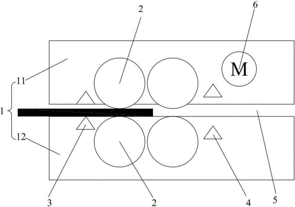
[0033] see figure 1 and figure 2 , an automatic card insertion and removal device for testing a card reader, comprising a housing 1, a rubber wheel 2 and a sensor.

[0034] The housing 1 includes an upper housing 11 and a lower housing 12 arranged at intervals up and down. The upper housing 11 and the lower housing 12 are fixedly connected by columns, and a card channel 5 is formed between the upper housing 11 and the lower housing 12 .

[0035] During the test, the card channel 5 is connected with the bayonet of the card reader. The connection method between the device and the card reader can be as follows: the card reader is taken out from the ATM machine, and it is jointly fixed with the device for control, and a piece of sheet metal needs to be used as the base to fix the card reader and the device at the same time; Can be: test on the whole ATM machine, fix the device on a vertical support, the height of the support can be adjusted, by moving the position of the suppor...

Embodiment 2

[0046] see image 3 and Figure 4 , where components identical or corresponding to those of the first embodiment adopt the reference numerals corresponding to those of the first embodiment. For simplicity, only the differences between the second embodiment and the first embodiment will be described. The difference is that, in order to facilitate the insertion of the card into the card passage 5, the rubber wheels 21 near the bayonet in one of the two sets of rubber wheels are rubber wheels 21 with notches, and the others are rubber wheels 22 without notches. The notch of the notched rubber wheel 21 is a plane. Correspondingly, the housing 1 is provided with a phase detection sensor 7 for detecting the phase of the notch of the notched rubber wheel 21 , that is, detecting whether the notch plane is flush with the card channel.

[0047] Each set of rubber wheels includes at least one rubber wheel. In this example, image 3 Among them, each group of rubber wheels 2 includes ...


PUM


Abstract

The invention discloses an automatic card insertion and taking device for testing a card reader and a control method, and belongs to the technical field of automated testing. The device includes a shell, rubber wheels and sensors, the shell includes an upper shell and a lower shell which are vertically arranged at an interval, a card channel is formed between the upper shell and the lower shell, and the card channel is connected with a card opening of the card reader; the two groups of rubber wheels are located on the upper shell and the lower shell respectively and directly face each other, can rotate under the driving of a motor, and are used for driving a card to move along the card channel; and the sensors include first sensors located at one sides of the rubber wheels close to the card opening and second sensors located at one sides of the rubber wheels away from the card opening. When the card reader returns the card, the device takes the card, when the card reader reads the card, the device inserts the card, thereby omitting actions of manual card insertion and taking, continuous card insertion / card taking tests can be carried out on the card reader, human cost is saved, and the automatic card insertion and taking device for testing the card reader is simple and practical in structure, convenient to operate, fast in speed, high in test efficiency and low in manufacturing cost.

Description

technical field [0001] The invention relates to the technical field of automatic testing, in particular to an automatic card insertion and removal device for testing a card reader and a control method thereof. Background technique [0002] An automated teller machine (ATM) is a highly sophisticated mechatronic device that utilizes magnetically coded cards or smart cards to facilitate financial transactions. ATM machines have been widely used in all aspects of social and economic life and have become one of the indispensable equipment. [0003] As an important part of the ATM, the card reader is used to read the user's information stored in the magnetic stripe card and IC card issued by the bank. Card readers need a lot of testing before use and during maintenance to verify the stability of the card reader hardware and the card reader control program to reduce the probability of failure. Existing test methods mainly include manual card insertion and card removal and mechani...

Claims


Application Information

Patent Timeline
IPC IPC(8): G06K7/00G07F19/00
CPCG06K7/0013G06K7/0095G07F19/209
Inventor 杜杨君
Owner SHENZHEN YIHUA COMP
Learn More