Sensorless driving system for three-phase motor of four-switch inverter
A technology for three-phase motors and drive systems, which is applied in the control of electromechanical transmissions, control systems, and generators, and can solve the problems of slow steady-state response, high cost, and symmetrical output of three-phase voltage signals.
- Summary
- Abstract
- Description
- Claims
- Application Information
AI Technical Summary
Problems solved by technology
Method used
Image
Examples
Embodiment 1
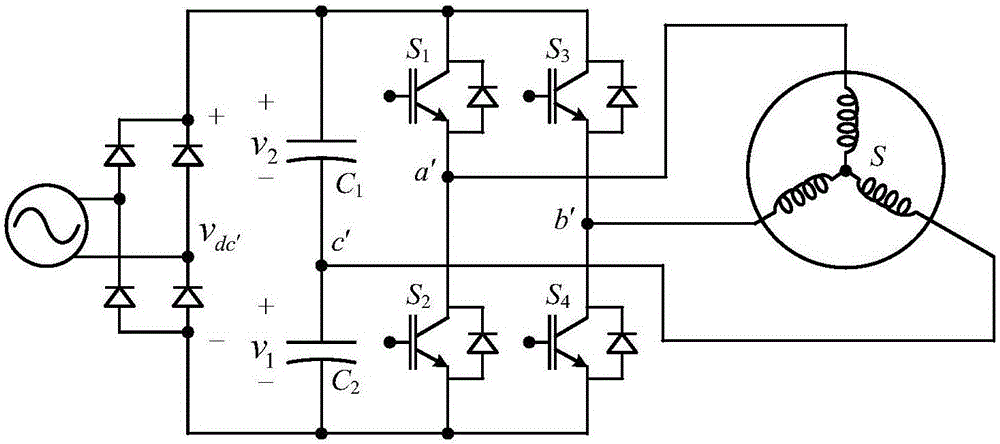
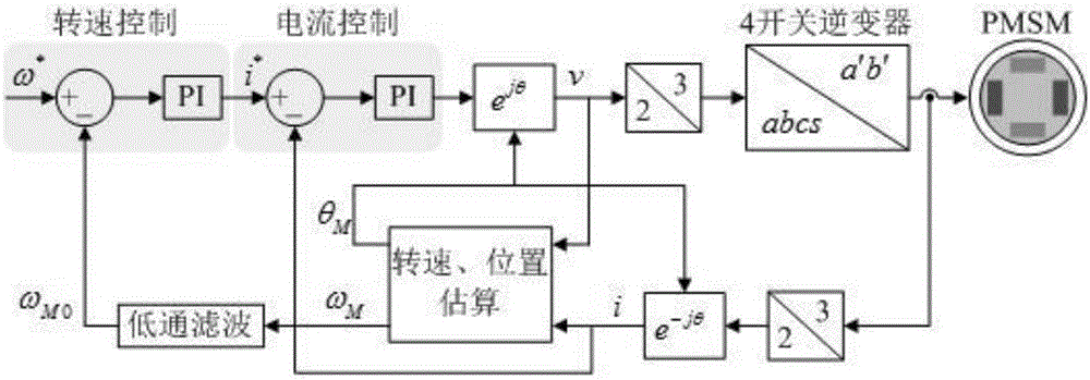
[0073] Example 1: see figure 1 , a four-switch inverter three-phase motor sensorless drive system, the four-switch inverter three-phase motor sensorless drive system includes a four-switch inverter input signal is a DC voltage, the DC voltage can be an inverter The output DC signal can also be the DC voltage output of the battery. The four-switch full-bridge inverter circuit includes two capacitors C1, C2 and four controllable switches S1-S4. The inverter has three voltage output ports, which are respectively connected to the three voltage input ports of the motor. The four switches are four IGBTs or GTOs and other controllable turn-on and turn-off thyristors, and the switch signals are generated by an ARM microprocessor. When the load is a motor, in order to achieve three-phase voltage output, the third phase of the motor is linked to the neutral point of a set of capacitors, and the neutral point potential is equivalent to the zero potential of the ground. The current sig...
Embodiment 2
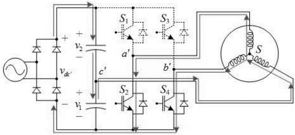
[0074] Example 2: see Figure 1-Figure 6 , a control method of a four-switch inverter three-phase motor sensorless drive system, the control method is as follows:
[0075] 1) as figure 1 As shown in the figure, in the four-switch inverter, only four switches can be controlled to be turned on and off, and the four switches are S in the figure. 1 , S 2 , S 3 , S 4 , C in the figure 1 , C 2 Indicates the capacitor, and its state is uncontrollable, so there are only four switch states. The switch table is shown below. In the table, 1 means the switch is closed, and 0 means the switch is open.
[0076] model S 1
S 2
S 3
S 4
1 0 1 0 1 2 0 1 1 0 3 1 0 0 1 4 1 0 1 0
[0077] Depend on figure 1 It can be seen that the DC side is powered by an uncontrolled rectifier bridge, and the C phase is connected to the midpoint of the DC capacitor, so the DC side voltage output v dc′ There are fluctuations. It can be seen tha...
PUM
 Abstract
Description
Claims
Application Information
 - R&D
- Intellectual Property
- Life Sciences
- Materials
- Tech Scout
- Unparalleled Data Quality
- Higher Quality Content
- 60% Fewer Hallucinations
Browse by: Latest US Patents, China's latest patents, Technical Efficacy Thesaurus, Application Domain, Technology Topic, Popular Technical Reports.
© 2025 PatSnap. All rights reserved.Legal|Privacy policy|Modern Slavery Act Transparency Statement|Sitemap|About US| Contact US: help@patsnap.com


