CL-FT-CL resonant current converter

A CL-FT-CL, resonant DC technology, applied in the direction of converting DC power input to DC power output, instruments, adjusting electrical variables, etc. narrow voltage range, only a single power converter, etc., to achieve the effect of broadening the power application range, facilitating parameter design, and improving efficiency

Active Publication Date: 2017-05-31
TIANJIN UNIV
View PDF4 Cites 1 Cited by
  • Summary
  • Abstract
  • Description
  • Claims
  • Application Information

AI Technical Summary

Problems solved by technology

However, these converters still have some problems that need to be solved urgently, including the inability to simultaneously turn on and turn off the soft switching of the power switch tubes, and the efficiency is limited; the input and output voltage ranges are narrow, which is not suitable for scenarios that require flexible adjustment of voltage levels; only There is a single power converter, considering the saturation of magnetic components, the limited transmission power of the converter, etc.

Method used


Image

  • CL-FT-CL resonant current converter
  • CL-FT-CL resonant current converter
  • CL-FT-CL resonant current converter

Examples


Embodiment Construction

[0022] Below in conjunction with accompanying drawing, the present invention will be further described:

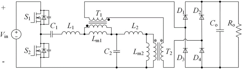
[0023] A CL-FT-CL resonant DC converter is composed of a half-bridge inverter circuit, a CL-FT-CL (capacitor inductance-flyback transformer-capacitor inductance) resonant circuit and a diode rectifier circuit connected in sequence, and the converter consists of the The input of the half-bridge inverter circuit is output from the diode rectifier circuit after the action of the CL-FT-CL resonant circuit; in the present embodiment, the half-bridge inverter circuit is composed of the first switching tube S 1 and the second switch tube S 2 Composition, CL-FT-CL resonant circuit is composed of the first capacitor C 1 , the second capacitance C 2 , the first inductance L 1 , the second inductance L 2 , flyback high frequency transformer T 1 and forward high frequency transformer T 2 Composed of, the diode rectifier circuit consists of the first diode D 1 , the second diode...


PUM


Abstract

The invention discloses a CL-FT-CL resonant current converter. The CL-FT-CL resonant current converter is composed of a half-bridge inversion circuit, a CL-FT-CL resonant circuit and a diode rectification circuit, which are connected in sequence; the converter is input through the half-bridge inversion circuit and is output from the diode rectification circuit through the action of the CL-FT-CL resonant circuit; the half-bridge inversion circuit is composed of a first switching tube and a second switching tube; the CL-FT-CL resonant circuit is composed of a first capacitor, a second capacitor, a first inductor, a second inductor, a flyback high-frequency transformer and a forward high-frequency transformer; dotted terminals of the flyback high-frequency transformer are not located at the same side; dotted terminals of the forward high-frequency transformer are located at the same side; power transmission capabilities of the converter can be expanded though the flyback high-frequency transformer and the forward high-frequency transformer; the CL-FT-CL resonant circuit can realize zero voltage switching and quasi-zero current switching of the switching tubes, and zero current switching of a diode; an input voltage range and an output voltage range of the circuit are expanded.

Description

technical field [0001] The invention belongs to a DC converter, in particular to a "capacitor inductance-flyback transformer-capacitor inductance (CL-FT-CL)" resonant DC converter with high efficiency, wide input and output range and high power. Background technique [0002] Now distributed power generation is an emerging energy utilization method. Compared with the traditional large-scale centralized fossil energy power generation method, it has the advantages of high environmental protection, strong sustainability, low cost, and flexible and adjustable installed capacity. It has attracted extensive attention from scholars at home and abroad. As an important part of power electronic devices in distributed power generation systems, DC converters play an important role. They have multiple functions and functions such as connecting different levels of DC buses, controlling DC voltage, and controlling battery charging and discharging. Research hotspots. [0003] In order to i...

Claims


Application Information

Patent Timeline
IPC IPC(8): H02M3/335
CPCH02M3/33569H02M1/0058Y02B70/10
Inventor 杨良王议锋王成山钟旭韦徵
Owner TIANJIN UNIV
Why Eureka
Try Eureka