
Wireless parallel transmission method for energy and signal shared channel

A technology of shared channel and transmission method, applied in the field of wireless power transmission, to achieve the effect of large bandwidth, large bandwidth range and reducing bit error rate

Active Publication Date: 2017-05-31
HARBIN INST OF TECH
View PDF4 Cites 7 Cited by
  • Summary
  • Abstract
  • Description
  • Claims
  • Application Information

AI Technical Summary

Problems solved by technology

[0003] The purpose of the present invention is to solve the problem that two channels are required for synchronous transmission of existing wireless energy and information, and to provide a wireless parallel transmission method for energy and signal sharing channels

Method used


Image

  • Wireless parallel transmission method for energy and signal shared channel
  • Wireless parallel transmission method for energy and signal shared channel
  • Wireless parallel transmission method for energy and signal shared channel

Examples


specific Embodiment approach 1

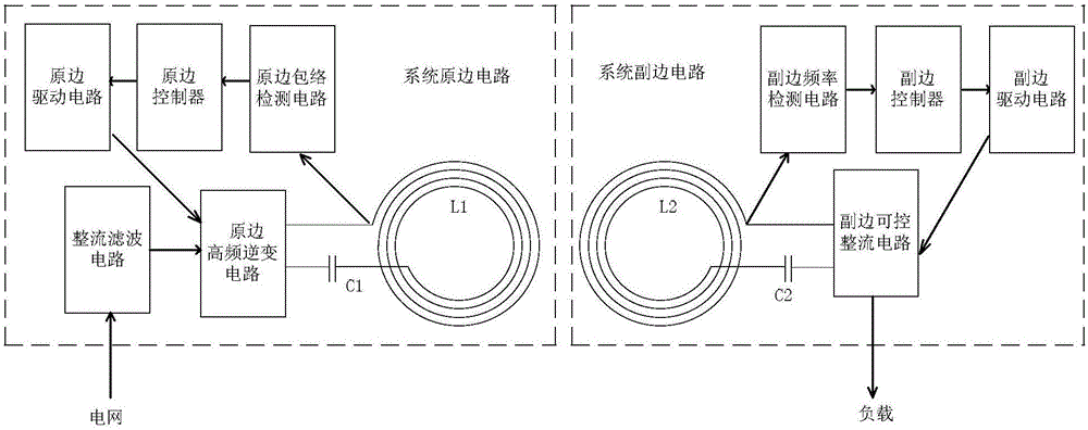
[0013] Specific implementation mode one: the following combination figure 1 Describe this embodiment, the wireless parallel transmission method of the energy and signal shared channel described in this embodiment, the system primary side circuit and the system secondary side circuit use a pair of coils as the shared channel, and use the same frequency to realize parallel synchronous transmission of information and energy; The primary circuit of the system uses frequency conversion to realize the forward transmission of information, and the secondary circuit of the system uses the method of controllable rectification to realize the reverse transmission of information.

specific Embodiment approach 2

[0014] Specific implementation mode two: the following combination Figure 1-Figure 3 This embodiment will be described. This embodiment will further explain the first embodiment. The primary side circuit of the system includes a rectification filter circuit, a primary side high frequency inverter circuit, a primary side envelope detection circuit, a primary side transmitting coil L1 and a primary side capacitor C1; The secondary side circuit of the system includes the secondary side receiving coil L2, the secondary side capacitor C2, the secondary side controllable rectification circuit and the secondary side frequency detection circuit;

[0015] The primary side circuit of the system is powered by the power grid, and a stable DC voltage is obtained through the rectification and filtering circuit, and an alternating voltage at a specified frequency is obtained through a high-frequency inverter. The primary side transmitting coil L1 and capacitor C1 induce an alternating magnet...

specific Embodiment approach 3

[0017] Embodiment 3: This embodiment further explains Embodiment 2. The specific process of detecting the duty ratio of the MOS tube drive signal waveform in the secondary side controllable rectification circuit by the primary side envelope detection circuit is: by detecting the current signal of the primary side Get the waveform of the driving signal on the secondary side.


PUM


Abstract

The invention relates to a wireless parallel transmission method for an energy and signal shared channel and belongs to the field of radio energy transmission. The wireless parallel transmission method is used for solving the problem that the implementation of synchronous transmission of wireless energy and information needs two channels. According to the wireless parallel transmission method for the energy and signal shared channel, provided by the invention, a system primary side circuit and a system secondary side circuit adopt a pair of coils as a shared channel and achieve the parallel synchronous transmission of the information and the energy by adopting the same frequency; the system primary side circuit achieves the forward transmission of the information in a variable frequency manner, and the system secondary side circuit achieves the reverse transmission of the information in a controllable rectifying manner. The method is applied to wireless radio energy transmission.

Description

technical field [0001] The invention relates to a wireless parallel transmission method for energy and signal sharing channels, belonging to the field of wireless energy transmission. Background technique [0002] Since Marin Sauljaksi and others from the Massachusetts Institute of Technology made new progress in the field of wireless power transmission in 2007, various research institutions at home and abroad have taken further explorations, gradually shifting from wireless to wireless. Energy transmission transitions to synchronous transmission of energy and information, but the existing wireless synchronous transmission of energy and information is usually limited to one-way transmission of energy and information, if two-way transmission is to be achieved, two channels are required. Contents of the invention [0003] The purpose of the present invention is to solve the problem that two channels are required for synchronous transmission of existing wireless energy and in...

Claims


Application Information

Patent Timeline
IPC IPC(8): H02J50/12H02J50/80
CPCH02J5/005
Inventor 宋凯朱春波刘凯珺李振杰姜金海魏国逯仁贵
Owner HARBIN INST OF TECH
Learn More