
A lccl resonant structure for compensating high order harmonic current by fundamental wave current

A resonant structure, high-order harmonic technology, applied in AC network to reduce harmonics/ripples, harmonic reduction devices, electrical components, etc., can solve problems such as large switching loss and inability to achieve

Active Publication Date: 2019-08-02
NAVAL UNIV OF ENG PLA
View PDF2 Cites 0 Cited by
  • Summary
  • Abstract
  • Description
  • Claims
  • Application Information

AI Technical Summary

Problems solved by technology

Therefore, the symmetrical LCL three-stage structure cannot achieve the effect that the input and output impedances are pure resistance.
At the switching moment of the ICPT system inverter, the instantaneous current value passing through the power tube is not zero, causing the inverter to be in a hard-off working state, resulting in large switching losses

Method used

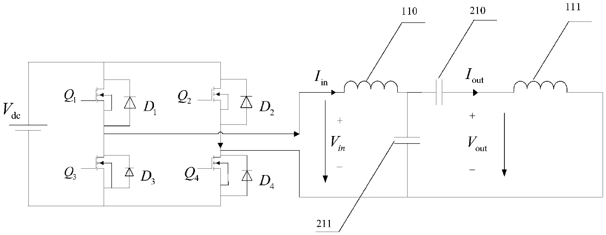

Image

  • A lccl resonant structure for compensating high order harmonic current by fundamental wave current
  • A lccl resonant structure for compensating high order harmonic current by fundamental wave current
  • A lccl resonant structure for compensating high order harmonic current by fundamental wave current

Examples


Embodiment Construction

[0117] In order to make the object, technical solution and advantages of the present invention clearer, the present invention will be further described in detail below in conjunction with the accompanying drawings. The specific embodiments described here are only used to explain the present invention, not to limit the present invention.

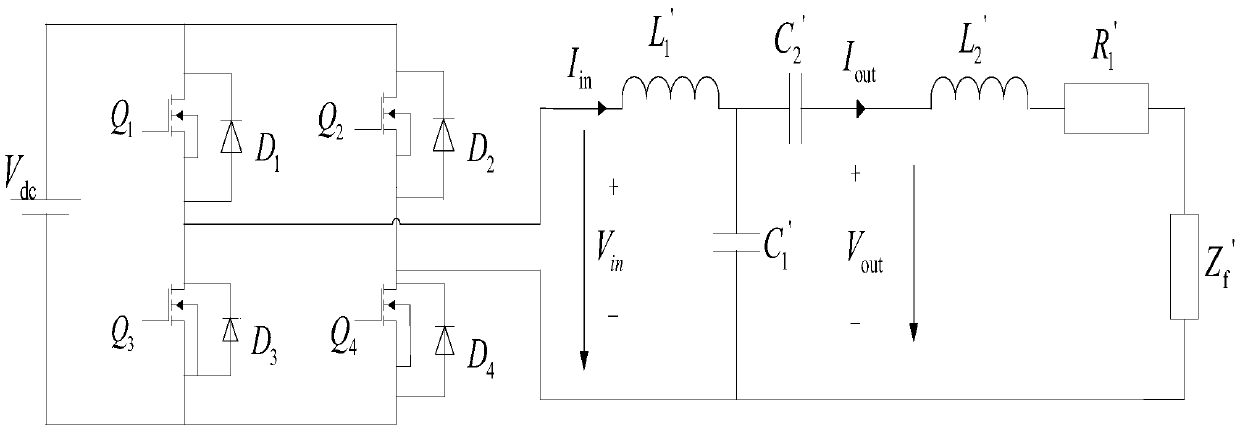
[0118] A kind of LCCL type resonant structure that the present invention proposes for ICPT system, such as figure 1 shown. The structure includes: resonant inductor 110, ICPT system power transmitting coil 111, parallel resonant capacitor 211, series resonant capacitor 210, after ICPT system power transmitting coil 111 is connected in series with series resonant capacitor 210, and then connected in parallel with parallel resonant capacitor 211, Then it is connected in series with the resonant inductor 110 . Its corresponding equivalent circuit is as figure 2 As shown, the equivalent circuit corresponding to this structure is: inductance ...


PUM


Abstract

The invention discloses an LCCL resonant structure for compensating a higher harmonic current by a basic wave current. The structure comprises a resonant inductor, an inductive contact-less power transfer (ICPT) system electric energy emission end coil, a parallel resonant capacitor and a series resonant capacitor, wherein the ICPT system electric energy emission end coil is connected in parallel with the parallel resonant capacitor and then is connected with the resonant inductor after being connected with the series resonant capacitor. The method for compensating the harmonic current of an input end of the LCCL resonant structure by the basic wave current of the input end of the LCCL resonant structure is employed, a parameter design relation of the structure is given, and the purpose that a full-bridge inverter of the ICPT system connected with the LCCL resonant structure works in a zero-current switch-off state is achieved.

Description

technical field [0001] The invention relates to the technical field of wireless power transmission, in particular to a resonant structure at a power transmitting end of an electromagnetic induction non-contact power transmission system. Background technique [0002] The electromagnetic induction wireless power transfer (Inductive Contactless Power Transfer, ICPT) system utilizes the principle of electromagnetic induction and adopts the method of electromagnetic resonance to realize the non-contact transmission of electric energy. Compared with the laser and microwave carrier methods, this technology has the advantages of not being affected by intermediate non-magnetic obstacles and having little impact on organisms. It is one of the best ways to transmit high-power electric energy in a short distance below 10m. ICPT technology provides a new feasible solution to solve the problems of mobile power supply for maglev trains, power supply for built-in medical equipment in confin...

Claims


Application Information

Patent Timeline
Patent Type & Authority Patents(China)
IPC IPC(8): H02J50/12H02J3/01
CPCH02J3/01Y02E40/40
Inventor 高键鑫吴旭升汪小娜高嵬
Owner NAVAL UNIV OF ENG PLA
Learn More