Electric heat-storage device configuration system
A configuration system, electric heat storage technology, applied in circuit devices, power network operating system integration, heat storage equipment, etc., can solve the problems of incapable unit peak regulation capability, unadjustable power range, and difficulty in adapting to large-area heating needs. , to achieve the effect of increasing flexibility and improving the ability of deep peak regulation
- Summary
- Abstract
- Description
- Claims
- Application Information
AI Technical Summary
Problems solved by technology
Method used
Image

Examples
Embodiment 1
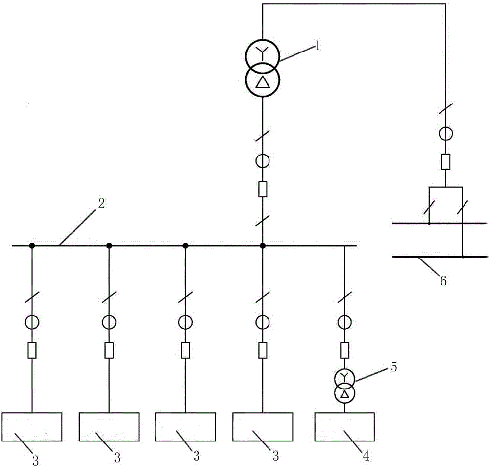
[0033] Such as figure 1 As shown, a system for configuring electric heat storage devices includes a peak-shaving system, a voltage transformation device and a power grid. The peak-shaving system is provided with multiple sets of solid electric heat storage devices 3, and a set of liquid electric heat storage devices 4 is set at the same time. The solid electric heat storage device 3 and the liquid electric heat storage device 4 are connected in parallel through a grid.
[0034] In this embodiment, the whole power plant is used as a unit, the power supply voltage of the electric heat storage device is selected as 66kV, and the liquid electric heat storage device 4 is selected as a high-power electrode hot water heater. A new incoming line interval is added to the original 220kV busbar 6 of the power plant, and after being adjusted to 66kV by a 220 / 66kV step-down transformer 1, it is used by the solid electric heat storage device 3, and the electric heat storage device is equipp...
Embodiment 2
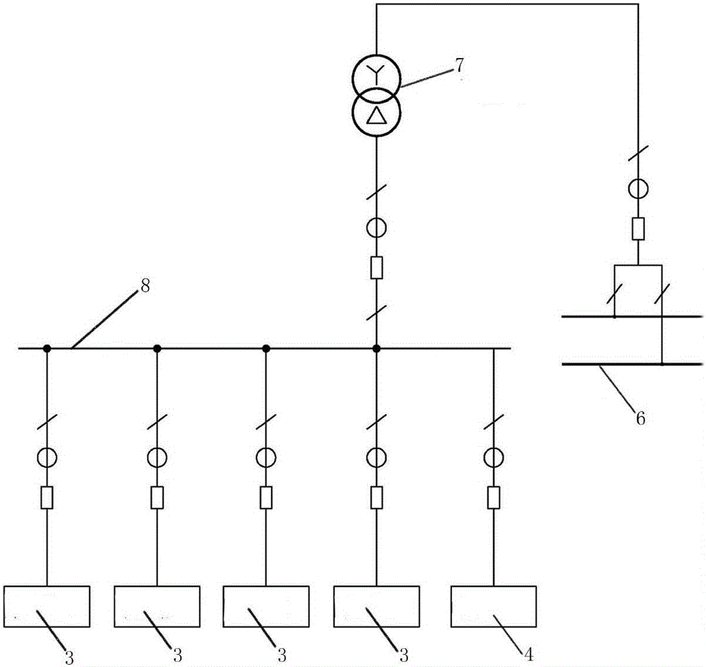
[0038] Such as figure 2 As shown, a system for configuring electric heat storage devices includes a peak-shaving system, a voltage transformer and a power grid. The peak-shaving system is provided with multiple sets of solid electric heat storage devices 3, and a set of liquid electric heat storage devices 4 is set at the same time. The solid electric heat storage device 3 and the liquid electric heat storage device 4 are connected in parallel through a grid.
[0039]In this embodiment, the whole power plant is taken as the whole unit. The liquid electric thermal storage device 4 uses a high-power electrode hot water heater, and the power supply voltage of the solid electric thermal storage device 3 and the electrode hot water heater device is selected as 20kV. A new incoming line interval is added to the original 220kV bus 6 of the power plant, and after being adjusted to 20kV by a 220 / 20kV step-down transformer 7, it is connected to the 20kV bus 8 to supply power for the el...
Embodiment 3
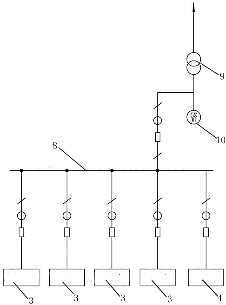
[0043] Such as image 3 As shown, a system for configuring electric heat storage devices includes a peak-shaving system, a voltage transformation device and a power grid. The peak-shaving system is provided with multiple sets of solid electric heat storage devices 3, and a set of liquid electric heat storage devices 4 is set at the same time. The solid electric heat storage device 3 and the liquid electric heat storage device 4 are connected in parallel through a grid.
[0044] In this embodiment, each unit is taken as a unit as a whole, and the voltage of the electric heat storage device is selected as 20kV, and the power is supplied by the 20kV bus 8 . The electric heat storage device is equipped with a 20kV bus switchgear on site as a normal start-stop control switch for the electric heat storage device. The total power supply of the 20kV bus 8 can be separated from the phase bus and directly connected to the 20kV main closed bus of the generator 10 through the outlet circ...
PUM
 Abstract
Description
Claims
Application Information
 - R&D
- Intellectual Property
- Life Sciences
- Materials
- Tech Scout
- Unparalleled Data Quality
- Higher Quality Content
- 60% Fewer Hallucinations
Browse by: Latest US Patents, China's latest patents, Technical Efficacy Thesaurus, Application Domain, Technology Topic, Popular Technical Reports.
© 2025 PatSnap. All rights reserved.Legal|Privacy policy|Modern Slavery Act Transparency Statement|Sitemap|About US| Contact US: help@patsnap.com